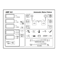
Terminal Name Description
1
Bat (+) Battery positive. Voltage must be between 9- 30 V
2
Bat (-) Battery negative. Battery negative must be connected
to earth.
3
Com 1 Common terminal of preheat, fuel solenoid and
cranking relays.
4
Preheat Preheat relay
5
Cranking Cranking relay
6
Fuel Solenoid Fuel or stop solenoid relay. Operating mode must be
selected from parameter menu.
7
Com 2 Common terminal of auxiliary relay 1, 2, 3
8,9,10
Aux. Output 1, 2, 3
Multiple function auxiliary relay outputs. Auxiliary
output 1 is default horn output.
11
HIGH
VOLTAGE
Mains Cont. Com.
Input terminal of mains contactor relay. Line R of
mains can be connected to this terminal
12
HIGH
VOLTAGE
Mains Cont. NC Output terminal of mains contactor relay. This output
is connected to mains contactor.
13
HIGH
VOLTAGE
Gen Cont. Com. Input terminal of generator contactor relay. Line U of
generator can be connected to this terminal
14
HIGH
VOLTAGE
Gen Cont. NO
Output terminal of generator contactor relay. This
output is connected to generator contactor.
15
Charge Fail Excit.
Warning lamp output of charge alternator must be
connected here. In the cranking excitation current is
supplied to charge alternator over 150 ohm resistor.
16
Aux. Input 1
Multiple function auxiliary input. These inputs are
activated if it is connected to battery negative. If oil
sender that have both sender and switch function is
used, switch terminal must be connected to this
terminal. Suitable configuration must be set for this
input to use it as oil pressure switch input. If this
input is used for auxiliary input. Alarm will be shown
as A1 in the display at the same time with auxiliary
led indication.
17
Aux. Input 2
Multiple function auxiliary input. These inputs are
activated if it is connected to battery negative. If
temperature sender that have both sender and switch
function is used, switch terminal must be connected to
this terminal. Suitable configuration must be set for
this input to use it as temperature switch input. If this
input is used for auxiliary input. Alarm will be shown
as A2 in the display at the same time with auxiliary
led indication.
 Loading...