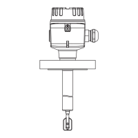
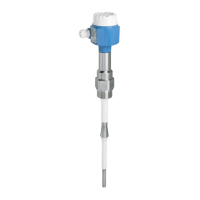
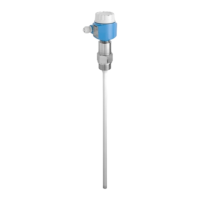
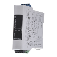
Liquiphant FTL64 Electrical connection
Endress+Hauser 15
6.3 Connecting the device
Housing thread
The thread of the electronics and connection compartment is coated with lubricant
varnish.
Avoid additional lubrication.
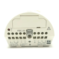
6.3.1 2-wire AC (electronic insert FEL61)
• Two-wire AC version
• Switches the load directly into the power supply circuit via an electronic switch; always
connect in series with a load
• Functional testing without level change
A functional test can be performed on the device using the test button on the electronic
insert.
Supply voltage
U = 19 to 253 V
AC
, 50 Hz/60 Hz
Residual voltage when switched through: typically 12 V
Observe the following as per IEC/EN61010-1: Provide a suitable circuit breaker for the
device, and limit the current to 1 A, e.g. by installing a 1 A fuse (slow-blow) in the phase
(not the neutral conductor) of the supply circuit.
Power consumption
S ≤ 2 VA
Current consumption
Residual current when blocked: I ≤ 3.8 mA
The red LED flashes in the event of an overload or short-circuit. Check for an overload or
short-circuit every 5 s. The test is deactivated after 60 s.
Connectable load
• Load with a minimum holding power/rated power of 2.5 VA at 253 V (10 mA) or 0.5 VA at
24 V (20 mA)
• Load with a maximum holding power/rated power of 89 VA at 253 V (350 mA) or 8.4 VA
at 24 V (350 mA)
• With overload and short-circuit protection
Behavior of output signal
• OK status: load on (switched through)
• Demand mode: load off (blocked)
• Alarm: load off (blocked)
Terminal assignment
Always connect an external load. The electronic insert has integrated short-circuit protection.

 Loading...


