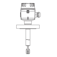
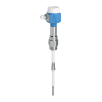
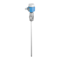
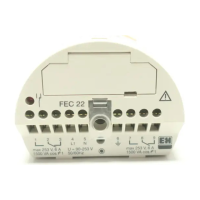
Electrical connection Liquiphant FTL64
32 Endress+Hauser
Behavior of switch output and signaling
MAX
RD YE GN
MIN
1
1
1
1
1
2
2
2
2
2
L+
L+
L+
L+
L+
2.2...3.8 mA
0.4...1.0 mA
2.2...3.8 mA
0.4...1.0 mA
< 1.0 mA
L-
L-
L-
L-
L-
A0037694
25 Behavior of switch output and signaling, electronic insert FEL68
MAXDIP switch for setting MAX safety mode
MIN DIP switch for setting MIN safety mode
RD Red LED for alarm
YE Yellow LED, switch status
GN Green LED, operational status, device on
The Bluetooth module for use in conjunction with the electronic insert FEL68 (2-wire
NAMUR) must be ordered separately with the necessary battery.
6.3.7 LED module VU120 (optional)
A brightly lit LED indicates the operational status (switch status or alarm status) in green,
yellow or red. The LED module can be connected to the following electronic inserts: FEL62,
FEL64, FEL64DC.
6.3.8 Bluetooth module VU121 (optional)
The Bluetooth module can be connected via the COM interface to the following electronic
inserts: FEL61, FEL62, FEL64, FEL64 DC, FEL67, FEL68 (2-wire NAMUR). In conjunction
with the electronic insert FEL68 (2-wire NAMUR), the Bluetooth module must be ordered
separately with the necessary battery.
6.3.9 Connecting the cables
Required tools
• Flat-blade screwdriver (0.6 mm x 3.5 mm) for terminals
• Suitable tool with width across flats AF24/25 (8 Nm (5.9 lbf ft)) for M20 cable gland

 Loading...


