12
3 Installation
Mechanical
connection
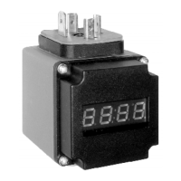
Fig. 1: Mechanical connection (display rotated 90° compared to delivery status)
• Insert the plug-on display ➁ between the plug ➂ and plug base ➀
of the sensor.
• Replace the fixing screw ➃ with the extended screw included in
the scope of delivery.
• Place seals between sensor/plug-on display and plug-on display/
plug.
• The display can be rotated 90°.
• A sticker which is included in the scope of delivery and contains
information on the technical unit can be affixed beneath the LED
display.
The plug-on display is ready for operation following installation.
ENDRESS+HAUSER
CERABAR T
PMP 131- ## # # # ###
SER No.
p
4…20 mA
IP 65 (1) (rd) + (2) (wt) –
1
2
3
4
P01-PHX2xxxx-17-xx-xx-xx-001
en