Do you have a question about the Endress+Hauser RIA 261 and is the answer not in the manual?
The unit must only be used within the specified temperature range and Ex documentation must be followed for hazardous areas.
Installation, commissioning, and maintenance must only be carried out by skilled and trained personnel following manual instructions.
National regulations must be followed for hazardous areas, ensuring skilled personnel are trained and adhere to all safety values.
Compare the order code on the unit legend plate with that on the delivery note to verify the correct unit.
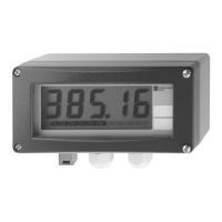
The unit is connected to a 4 to 20 mA current circuit, powered by it, and displays the measured value and bargraph.
Description of the micro-controller controlled display with numeric and analogue LC display, and internal resistor details.
Details regarding installation conditions, including dimensions of the unit.
Provides the physical dimensions of the field display unit.
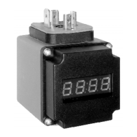
Information on mounting the unit, including suitability for wall mounting and optional adaptors.
Step-by-step instructions for mounting the unit directly onto a wall.
General information about electrical connections and terminal layout.
Details the terminal layout for the 4 to 20 mA circuit and further instrumentation.
Explains the electrical connection conforming to Ex requirements and the use of the earthing lug.
Introduction to the commissioning and operation sections, applicable to both Ex and non-Ex versions.
Overview of the operating menu parameters like Decimal point, Display value, and Offset.
Check wiring tightness and ensure terminal screws are tight for continuous safe operation.
The unit is ready for use once installation and wiring are complete.
Warning: Fault diagnosis on Ex units must NOT be made on an open unit to avoid invalidating protection classification.
Details the input type (Current), measurement range (4 to 20 mA), max input current, and voltage drop.
Describes the output signal, fault signal behavior, and HART protocol transmission.
Information on electrical connection, supply source (4 to 20 mA loop), and voltage drop.
Provides accuracy details, including measurement error and temperature drift.
Specifies installation angle, ambient temperature, storage temperature, climatic class, and ingress protection.
Details RF protection standards.
Lists standards for ESD, electromagnetic fields, burst, surge, and cable high frequency.
Details dimensions, weight, materials, terminals, cable entry, and pressure compensation.
Describes the LC display characteristics, display range, offset, and operation method.
Provides information on CE mark, Ex certification, and Marine approval.
| Device Type | Process indicator |
|---|---|
| Housing material | Aluminum |
| Protection | IP66 |
| Input signal | 4-20 mA, HART |
| Display | LCD |
| Accuracy | ±0.1% of full scale |