A DJM3
IOM-17 24 of 27 Mar 99 R3
BMSSignalCalibration
1. Apply100%mAorVdcsignaltotheDJM3“+”and“‐”terminals(i.e.10Vdcor20mA).
2. RecordthesettingsofDIPswitches1,2,and3.TurnoffDIPswitches1,2,and3.
3. MeasuretheDJM3calculatedsetpointatmultimetertestpointSPCusingaDCvoltmeter.
4. TurnDIPswitch1on.
5. MeasuretheDJM3calculatedset‐pointDCvoltageagainandadjusttheBMSCALPotuntilthe
voltageisequaltothenumberof°Cmaximumreset.
6. ReturntheDIPswitchestotheirnormalposition.
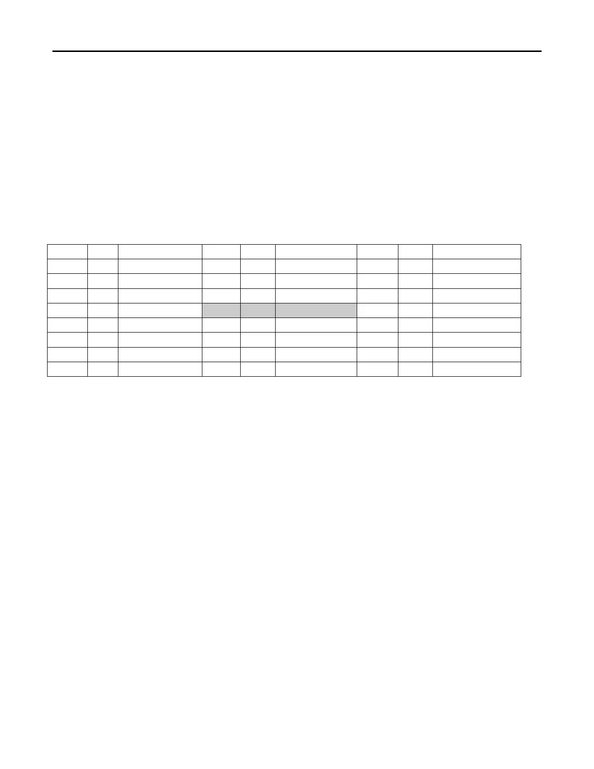
SENSORTABLE
SensorResistanceChartforTE6100‐960andTE6000EA3.
Table13
˚C ˚F ResistanceΩ ˚C ˚F ResistanceΩ ˚C ˚F ResistanceΩ
‐40 ‐40 597 4.4 40 877 48.9 120 1229
‐34.4 ‐30 629 10 50 916 54.4 130 1279
‐28.9 ‐20 661 15.6 60 958 60 140 1329
‐23.3 ‐10 694 21.1 70 1000 65.6 150 1381
‐17.8 0 728 26.7 80 1043 71.1 160 1433
‐12.2 10 763 32.2 90 1088 76.7 170 1487
‐6.6 20 800 37.8 100 1134 82.2 180 1542
‐1.1 30 838 43.3 110 1181 87.8 190 1599
Note:Referenceresistanceis1035ohmsat77˚F.Resistancetolerancesare±0.05to0.15%at77˚F.