A G-TRAC2
IOM-25 10 of 42 Mar 99 R7
NOTE: XXX Switch position does not affect description in “ACTION” box.
NORMAL OPERATION (PI control). (No BMS on C-TRAC direct
control but may be reset control)
Direct C-TRAC3 control (reduced integral control).
@ Direct BMS 010 VDC control (proportional control only).
* Set-up sheet Section XX.
If the low limit is required a discharge sensor must be connected to terminals Q and U and jumper U to S. If the low limit is not required jumper
terminals Q to U.
When using direct control, by C-TRAC on BMS terminal S must be connected to terminal U. Dipswitch A-1 must be in the off position (BMS reset
disabled).
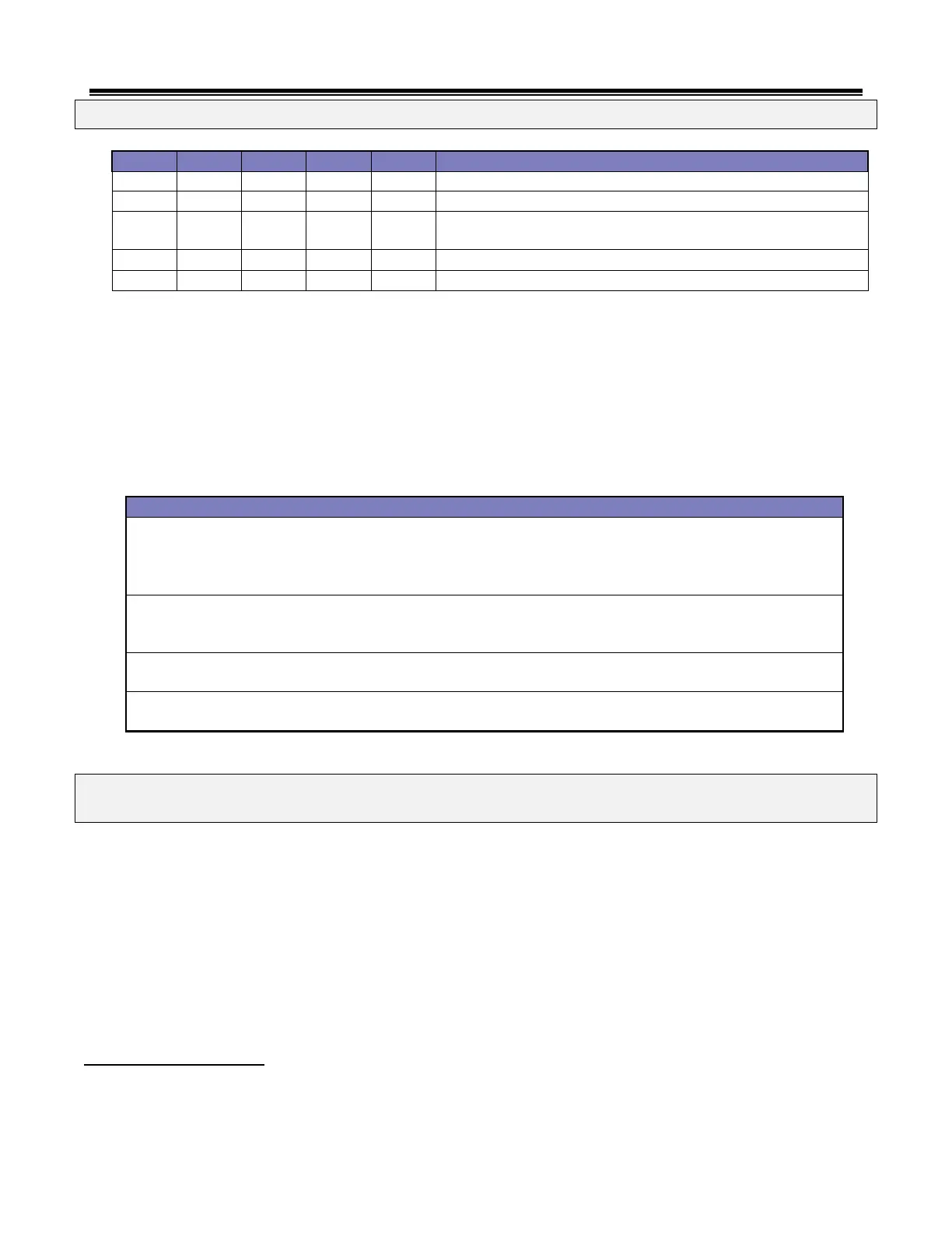
IX. POTS
The G-TRAC2 has 10 adjustable trim pots.
Discharge sensor calibration.
Discharge set-point calibration.
Voltage or current input calibration. This pot is also used for direct 010 VDC
control calibration.
Reset ratio for ambient and room reset.
Room thermostat calibration.
Night operation discharge set point.
Burner manual firing service pot.
Burner minimum firing rate.
High fire combustion air setting.
Low fire combustion air setting.
NOTE: Do not adjust any pot without fully reading and understanding the correct adjustment procedure for that
pot.
X. STATUS LIGHTS
There are 4 LED lights, which can indicate 20 various operation modes, status and/or fault codes. These lights have different
meanings based on their rate of flashing.
Slow Flash (1 second on, 1 second off)
Fast Flash (¼ second on, ¼ second off)
Irregular (2 short ‘on’ flashes followed by a long ‘off’)
The GTRAC-2 faceplate has a reference chart to indicate it.
LED 1 Burner Pre-Purge
Off The heat exchanger ignition pre-purge is completed or the combustion blower is not required to run.
Slow Flash The combustion blower is on and at pre-purge position, but the combustion air-proving switch is open.