A G-TRAC2
IOM-25 29 of 42 Mar 99 R7
SET-POINT READOUT AND DISCHARGE TEMPERATURE
FROM VOLTAGE ON READOUT PINS
XX. DISCHARGE TEMPERATURE READOUT
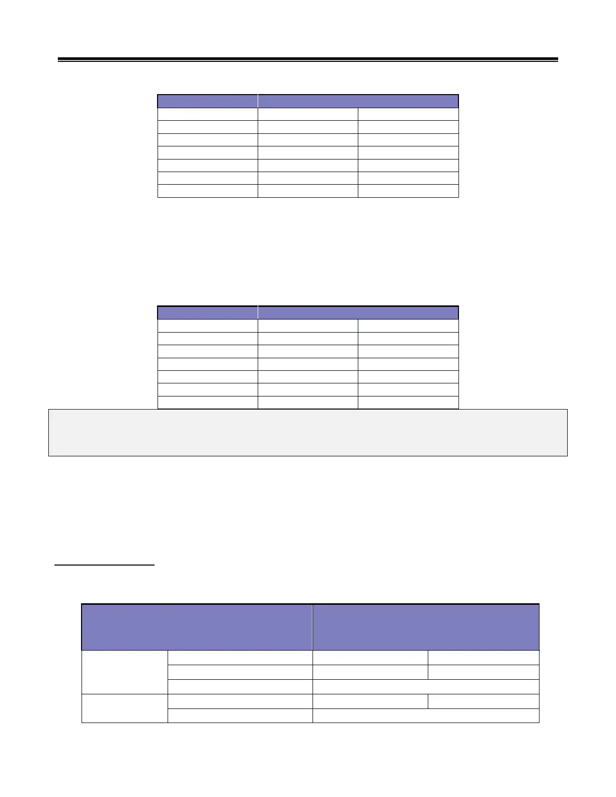
The discharge temperature at the temperature sensor can be obtained by measuring the voltage across spade connector
terminals “DTEMP” to “COMMON”. The readings are based on 10ºC per volt. (Example: A reading of 2.15 volts = 21.5ºC.)
ACTUAL TEMPERATURE READOUT FROM VOLTAGE ON READOUT PINS
NOTE: The readable range is 0 to 55ºC. At higher temperatures the reading accuracy is reduced. Typically at 50ºC
the reading will indicate 2-3ºC lower than actual.
NOTE: The readout is designed to be accurate from 10 to 30ºC.
If checking discharge air temperature with another thermometer, ensure it is located immediately next to the G-TRAC2
sensor. (See “Calibration”, Section XX, page 29).
XXI. DISCHARGE SENSOR READOUTS, CALIBRATION, ETC.
TE6100 Resistance’s
SENSOR (purple and blue wires) – same resistance as TE6000-960 (refer to the following chart).
Set Point Dialed to
60 degrees 90 degrees
About 1.981 K (varies with element temp.)