9
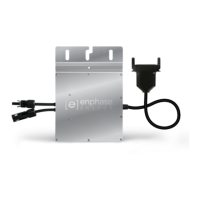
Terminate the Unused End of the Cable
a. Remove 60 mm (2.5”) of the cable sheath from
the conductors.
8
c. Slide the hex nut onto the cable.
d. Insert the cable end all the way into the wire
organizer (up to the stop).
e. Attach the cap.
hex
nut
wire
organizer
cap
f. Attach the terminated cable end to the PV
racking with a cable clip or tie wrap.
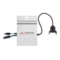
Connect the Cable to the AC Junction Box
Connect the Engage Cable into the AC branch circuit
junction box. See notes in Step Details.
bend wires down
into recesses of wire
organizer and trim to
length
place cap over
the wire organizer
hold the cap
with the discon-
nect tool or a #2
screwdriver
rotate the hex nut
with your hand or
a wrench until the
latching mechanism
meets the base–
do not over torque
b. Check that all terminator parts are present.
Never unscrew the hex nut. This action
can twist and damage the cable.
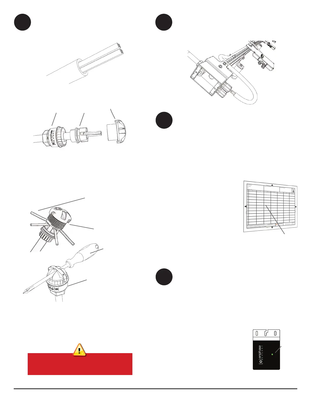
Complete the Installation Map
Build the system map manually, or use the ArrayGun
feature from the Enphase Installer Toolkit to easily
build and congure a system. For more information,
refer to http://enphase.com/products/arraygun.
To manually build the Installation Map:
a. Peel the removable serial number label from each
microinverter and afx it to the respective location
on the installation map included with this guide.
b. Peel the label from the Envoy and afx it to the
installation map.
c. Log in to Enlighten.
d. Scan the installation
map and upload it to the
System Activation form
online.
e. Use Array Builder to cre-
ate the virtual array using
the installation map as
your reference.
f. Refer to the Array Builder
demo at
http://enphase.com/support/videos.
afx serial
number labels
10
11
Connect the PV Modules
a. Mount the PV modules above the microinverters.
b. Connect the DC leads of each PV module to the
DC input connectors of their corresponding micro-
inverter.
The status LED on the underside of each M215
lights green six seconds after DC power is
applied. It remains lit solid for two minutes, fol-
lowed by six green blinks.
After that, red blinks indicate
that no grid is present. This is
because the AC circuit is not
yet energized.
status
LED
 Loading...