disconnect
tool
10
Enphase Energy, Inc.
1420 N. McDowell Blvd.
Petaluma, CA 94954
USA
info@enphaseenergy.com
http://www.enphase.com
© 2013 Enphase Energy Inc. All rights reserved.
Energize the System
a. If applicable, turn ON the AC disconnect or circuit
breaker for the branch circuit.
b. Turn ON the main utility-grid AC circuit breaker.
Your system will start producing power after a
ve-minute wait time.
Step Details
NOTE: Verify that AC voltage at the site is within range:
240 Volt AC Single-Phase 208 Volt AC Three-Phase
L1 to L2 211 to 264 VAC L1 to L2 to L3 183 to 229 VAC
L1, L2, to N 106 to 132 VAC L1, L2, L3 to N 106 to 132 VAC
WARNING: Only use electrical system components approved
for wet locations.
WARNING: Do not exceed the maximum number of microin-
verters in an AC branch circuit as listed in the table below. Each
branch circuit must be protected by a dedicated circuit breaker
of 20 A or less.
Service type Max M250s per branch
240 VAC single-phase 16
208 VAC three-phase 24
WARNING: Size the AC wire gauge to account for voltage drop
for both the branch circuit and all upstream conductors lead-
ing back to the PCC. See Circuit Calculations for M250 at
http://www.enphase.com/support.
DANGER: ELECTRIC SHOCK HAZARD. THE DC
CONDUCTORS OF THIS PHOTOVOLTAIC SYSTEM ARE
UNGROUNDED AND MAY BE ENERGIZED.
WARNING: Allow a minimum of 1.9 cm (0.75”) between the
roof and the microinverter. Also allow 1.3 cm (0.50”) between
the back of the PV module and the top of the microinverter.
NOTE: Torque the microinverter fasteners to the values shown.
Do not over torque:
• 1/4” mounting hardware – 5 N m (45-50 in-lbs)
• 5/16” mounting hardware – 9 N m (80-85 in-lbs)
Using a power screwdriver is not recommended due to the risk
of thread galling.
NOTE: The AC output neutral is not bonded to ground inside
the microinverter.
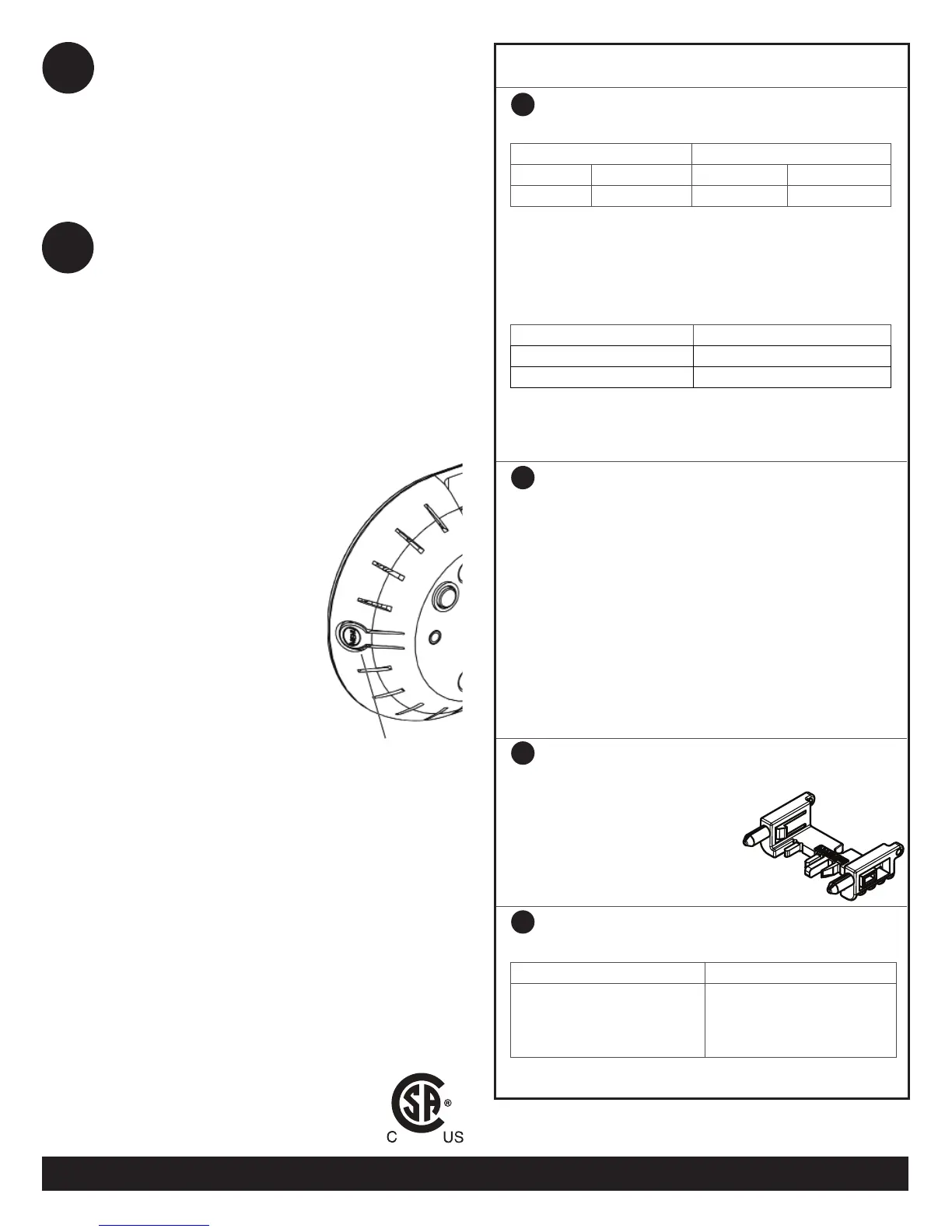
WARNING: Install sealing caps on all unused AC connectors
as these become live when the system is
energized by the utility. The IP67-rated
sealing caps are required for
protection against moisture ingress.
NOTE: To remove a sealing cap, you
must use the Enphase disconnect tool or
a #3 Phillips screwdriver.
NOTE: The Engage Cable uses the following wiring scheme.
240 Volt AC Single-Phase Wires 208 Volt AC Three-Phase Wires
Black – L1
Red – L2
White – Neutral
Green – Ground
Black – L1
Red – L2
Blue – L3
White – Neutral
Green – Ground
NOTE: The green wire acts as equipment ground (EGC).
2
3
5
7
11
Use the Envoy to Complete System Setup
Refer to the to the Envoy Quick Install Guide for
details on the following steps:
a. An automatic device scan runs for eight hours af-
ter the Envoy is installed. If this scan has expired,
start a new scan:
• Press and hold the Envoy menu button (on the
right side of the Envoy).
• Release the menu button when the LCD screen
displays Enable Device Scan.
b. Check that the LCD shows a
complete device count after
about 30 minutes.
c. Use the Envoy menu button
to select Enable Commu-
nication Check. Ensure at
least three level bars show
on the LCD.
d. When all devices are de-
tected, stop the scan. To do
this, use the Envoy menu
button to select Disable
Device Scan.
Envoy menu
button
(rear view)
 Loading...