2-3
3. Lock the Access Point in Place – To prevent unauthorized removal of the access
point, you can use a Kensington Slim MicroSaver security cable (not included) to
attach the access point to a fixed object.
4. Connect the Power Cord – Connect the power adapter to the access point, and the
power cord to an AC power outlet.
Otherwise, the access point can derive its operating power directly from the RJ-45
port when connected to a device that provides IEEE 802.3af compliant Power over
Ethernet (PoE).
Note: If the access point is connected to both a PoE source device and an AC power source,
AC will be disabled.
5. Observe the Self Test – When you power on the access point, verify that the Power
indicator stops flashing and remains on, and that the other indicators start
functioning as described under “LED Indicators” on page 1-4.
If the PWR LED does not stop flashing, the self test has not completed correctly.
Refer to “Troubleshooting” on page A-1.
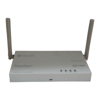
6. Connect the Ethernet Cable – The access point can be wired to a 10/100 Mbps
Ethernet through a network device such as a hub or a switch. Connect your network
to the RJ-45 port on the back panel with category 3, or 4 UTP Ethernet cable. When
the access point and the connected device are powered on, the Ethernet Link LED
should light indicating a valid network connection.
Note: The RJ-45 port on the access point supports automatic MDI/MDI-X operation, so you
can use straight-through cables for all network connections to PCs, switches, or hubs.
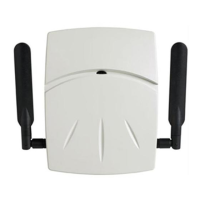
7. Position the Antennas – Each antenna emits a radiation pattern that is toroidal
(doughnut shaped), with the coverage extending most in the direction perpendicular
to the antenna. Therefore, the antennas should be oriented so that the radio
coverage pattern fills the intended horizontal space. Also, the diversity antennas
should both be positioned along the same axes, providing the same coverage area.
For example, if the access point is mounted on a horizontal surface, both antennas
should be positioned pointing vertically up to provide optimum coverage.
8. Connect the Console Port – Connect the console cable (included with RBT-4102)
to the RS-232 console port for accessing the command-line interface. You can
manage the access point using the console port, the web interface, or SNMP
management software such as Enterasys NetSight, or HP’s OpenView.
Warning: Use ONLY the power adapter supplied with this access point.
Otherwise, the product may be damaged.
Peligro: Use SOLAMENTE la fuente de alimentación que se incluye con el
punto de acceso. De lo contrario, el producto podría dañarse.
Achtung:
Verwenden Sie AUSSCHLIESSLICH das im Lieferumfang
enthaltene Netzteil für diesen Access Point. Anderenfalls besteht
die Gefahr, dass das Produkt beschädigt wird.
 Loading...