Page 11
710233A
,1,7,$7,217:267$*(3,/27
This control may be initiated by the closure of a two stage pilot. First stage is connected to
TS1-FS1 and TS1-GND, second stage is connected to TS1-FS3 and TS1-GND. The first
stage only activates the selected solenoid valve for the selected schedule, and does NOT
initiate a sequence. Once the control is initiated, via FS3, FS1 need not remain closed. The
initiation circuit is automatically clamped to prevent re-initiation until after the control has
completed its sequence. In the REPEAT MODE the control will continue to sequence as
long as the initiation remains closed.
,1,7,$7,216,1*/(67$*(3,/27
This control may be initiated by the closure of a single stage pilot. The pilot switch is
connected between TS1-FS3 and TS1-GND terminals. Once the control is initiated, the
switch need not remain closed. The initiation circuit is automatically clamped to prevent
re-initiation until after the control has completed the sequence. No connection is made to
TS1-FS1.
See also section 5.2 CUSTOMER TERMINAL STRIP DIAGRAMS.
,1,7,$7,21%($723(5$7,21
This control can be converted to BEAT OPERATION by use of the EXTENDED
FUNCTIONS. See section 7.10. Several different modes are available.
27+(5&+$5$&7(5,67,&6
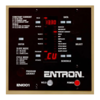
:(/'12:(/'6:,7&+ (1) and LED INDICATORS (2,3)
When the control is in NO WELD, the NO WELD LED (2) is illuminated. This allows the
control to be initiated without passing current through the welding transformer. When the
WELD LED (3) is illuminated, the SCR contactor will pass current through the welding
transformer during the programmed weld time. To toggle between these two modes simply
depress the WELD/NO WELD Push Button (1).
35(6685( 6:,7&+: If the pressure switch is not activated (open), the control will
advance through SQUEEZE Time and wait until the pressure switch closes before advancing
to WELD Time. The SQUEEZE LED will begin flashing at the end of SQUEEZE Time and
continue until the Pressure Switch closes. When the Pressure Switch closes, the control will
begin WELD Time and complete the sequence. It may be desired to set Squeeze count to 00.
This allows the weld sequence to begin immediately upon closure of the Pressure Switch.
If the Pressure Switch interrupts the sequence for an extended period the display will flash
the ERROR CODE # 15. This error will not terminate the weld sequence. Once the Pressure
Switch closes the sequence will continue on to weld time and complete the sequence.
See also section 5.3 CUSTOMER TERMINAL STRIP CONNECTIONS.
NOTE: Jumper TS1-PS1 and TS1-GND if pressure switch is not used. A Pressure Switch
is not furnished with the control.

 Loading...