Page 10
9$/9( 02'( (15) - The three solenoid valves are activated based on the code
programmed as shown in Table 1 below.
7$%/(
CODE TS1-SV1 TS1-SV3 TS1-SV5
--------------------------------------------------------------------
00
--------------------------------------------------------------------
01
X
--------------------------------------------------------------------
02
X
--------------------------------------------------------------------
03
X
X
--------------------------------------------------------------------
04
X
--------------------------------------------------------------------
05
X
X
--------------------------------------------------------------------
06
X
X
--------------------------------------------------------------------
07
X
X X
--------------------------------------------------------------------
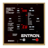
When in the PROGRAM mode and selection of a valve code is being
made, the valve LED indicators (28,30,31) will indicate the selected
valve /s (the valve /s output will not be energized while in program
mode).
NOTE: The valve code indicated above can be altered for different
features such as PROCESS OUTPUT. See section 7.3 EXTENDED
FUNCTIONS.
Change of '$7$',63/$<: Push Buttons (5) and (6), Display (4).
Change of the data displays can only be performed in PROGRAM MODE. Use Push Button
switches (5) and (6) to change the display. Push Button (5) increments the 10's digit by one
and Push Button (6) increments the 1's digit by one. When either digit reaches the maximum,
the DATA display resets to zero. When the desired data is displayed, data is entered by Push
Button switch (29).
(17(56ZLWFK: Push Button switch (29).
This switch is used to enter the data displayed in the DATA Display (4) into the non-volatile
memory.

 Loading...