Page 44
23(5$7,1*02'(6
For the instruction manual discussion on Operating Modes, the following abbreviations will
be used:
SQ
. . . SQUEEZE TIME
WE
. . WELD TIME
CO
. . . COOL TIME
HO
. . . HOLD TIME
OF
. . . OFF TIME
IMP
. . NUMBER OF IMPULSES
INIT
. . INITIATION OF SEQUENCE
NOTE:
Also refer to the Mode and Function selection information printed on the Control
panel.
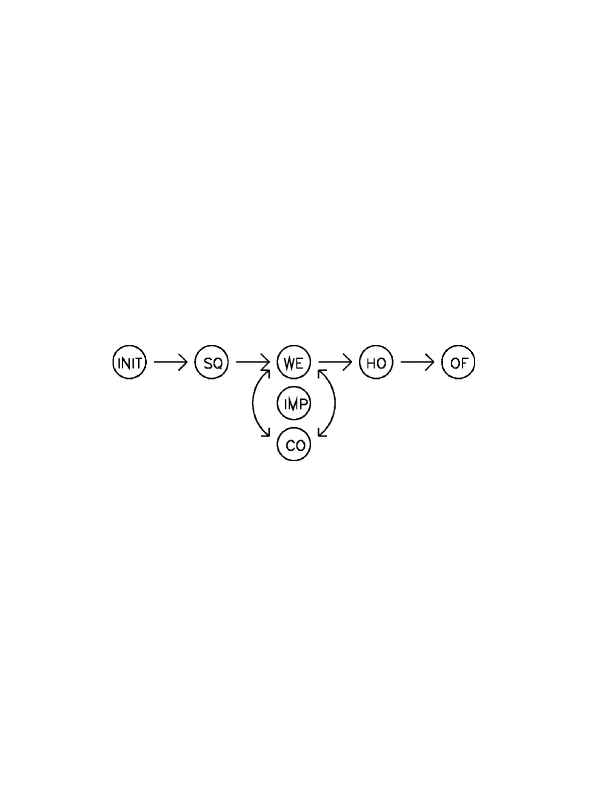
1215(3($7
: [00] IN CYCLE MODE FUNCTION (16).
When a SCHEDULE is initiated by a pilot switch connected to TS1-FS3 the sequence is as
follows: INIT-SQ-WE-CO-...-WE-HO-OF with the "..." representing "WE-CO" repeated as
many times as the IMP FUNCTION indicates. See FIGURE 2 below.
FIGURE 2.
Upon initiation, the programmed valve in VALVE MODE FUNCTION (18) is energized
at the beginning of SQ.
If the Pressure Switch is open the control counts SQ but does not begin counting WE time,
and remains stopped at that point in the sequence until the Pressure Switch closes, then WE
time counting begins and the SCHEDULE will continue to completion. If the Pressure
Switch remains open the SQUEEZE LED (7) will flash.
Weld current is then supplied to the welding transformer at a value programmed by the
PERCENT CURRENT for the WE period.
During CO welding current is not present, but the selected valve will still be energized. The
same occurs in HO. When OF begins, all solenoid valves are de-energized.
See section 7.3 EXTENDED FUNCTIONS.

 Loading...
