Envertech EVT800 Quick Installation
Guide
Please read and follow the safety and installation
instructions below. You can find and download
the instructions or other technical documents on
our website: www.envertec.com .
Official Website
1. Accessories
M8 x 25 screws (Prepared by the installer)
12
User Identification Number
-40℃ to +65℃
Temperature(℃):
Operating Range (Vdc):
16V~60V
Normal Voltage?(Vac):
220/230V
MPPT Voltage Range (Vdc):
22V~50V
Current (Max. Continuous) (A):
3.63A
Max. DC Input (Vdc):
60V
Frequency?(Hz):
50Hz/60Hz
Max. Input Continuous Current?(A):
14Ax2
Power Factor Range:
+/-0.90
Max. Input Short-Circuit Current (A):
25A Maximum Units Per Branch: 6
Power (Max. Continuous) (W):
800W
Overvoltage Category: OVC III (AC Main), OVC II ( PV)
Ingress Protection (IP):
IP67 Protective Class: Class I
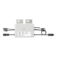
Model: EVT800
www.envertec.com
Envertech(Shanghai)Corporation LTD.
PV Microinverter
Note: All accessories above are not included in
the package and should be purchased separate-
ly.
2. Create an Installation Map
a. Create a paper installation map to record mi-
croinverter serial numbers and positions in the
array. Download the sheet with this QR code.
Installation Map
b. Peel the removable serial number label from
each microinverter and affix it to the respec-
tive location on the paper installation map.
12
User Identification Num ber
-40℃ to +65℃
Temp erature(℃):
OperatingRange(Vdc):
16V~6 0V
Normal Voltage?(Vac):
220/23 0V
MPPT VoltageRange(Vdc):
22V~5 0V
Current (Max.Continuous) (A):
3.63A
Max. DC Input (Vdc):
60V
Frequency?( Hz):
Max. Input Continuo us Curre nt?(A) :
14Ax2
Power FactorRange:
+/-0.90
Max. Input Short-Circuit Current (A):
25A Maximum UnitsPerBranch: 6
Power (Max . Continuous) (W):
80 0W
Overvoltage Categ ory: OVCIII (ACMain), OVC II (PV)
IngressProtection(IP):
IP67 Protective Class: Class I
M odel: EV T800
www.envertec.com
Envertech(Shanghai)CorporationLTD.
PV M ic roinv ert er
PV M odule
M icroinverter
PV M odule
Extension cable
Cable End C ap
CN 23 05 20 30 59 60 01 CN23 05 20 30 59 60 00
c. Always keep a copy of the installation map for
your records.
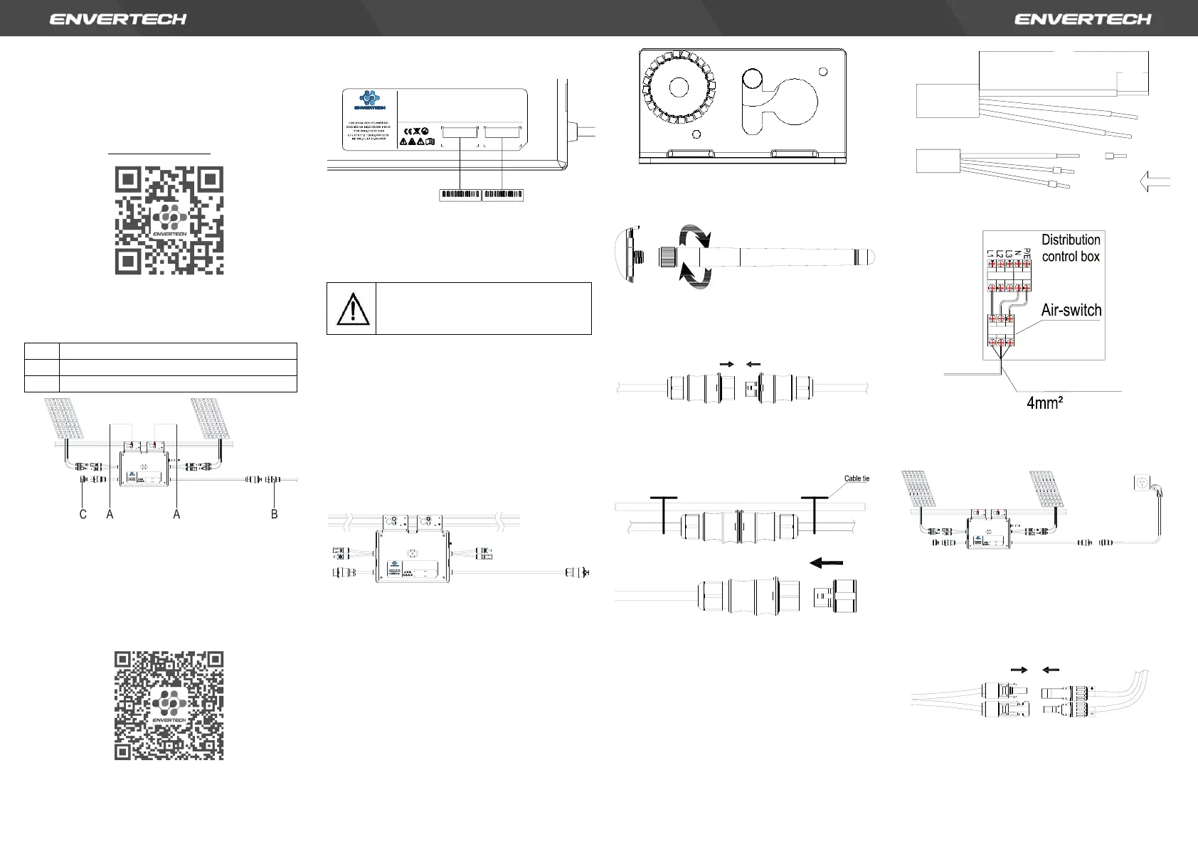
3. Installation Steps
Step 1. Verify that grid voltage and PV panel
voltage match with microinverter rating
Step 2. Mount microinverters onto the rack
Mark out the estimated center of each PV mod-
ule on the rack to facilitate locating microinvert-
ers.
Mount all microinverters under modules to avoid
rain and sun, with the trademark facing down-
ward.
Note: Please make sure that there are less than
7 units of EVT800 in each branch (12AWG).
12
User Identification Number
-40℃ to +65℃
Temperature(℃):
Operating Range (Vdc):
16V~60V
Normal Voltage?(Vac):
220/230V
MPPT Voltage Range (Vdc):
22V~50V
Current (Max. Continuous) (A):
3.63A
Max. DC Input (Vdc):
60V
Frequency?(Hz):
50Hz/60Hz
Max. Input Continuous Current?(A):
14Ax2
Power Factor Range:
+/-0.90
Max. Input Short-Circuit Current (A):
25A Maximum Units Per Branch: 6
Power (Max. Continuous) (W):
800W
Overvoltage Category: OVC III (AC Main), OVC II ( PV)
Ingress Protection (IP):
IP67 Protective Class: Class I
Model: EVT800
www.envertec.com
Envertech(Shanghai)Corporation LTD.
PV Microinverter
Step 3. Ground the system
Microinverters and modules must be connected
to the grounding conductor in accordance with
national standards. Fix the screws to the mi-
croinverter installation hole. Make sure that the
grounding screw thread is pierced into the
bracket to get the best grounding effect.
Step 4. Install a WLAN antenna
For better WiFi signal, rotate the antenna
clockwise until it is firmly secured to the EVT800.
Step 5. Connect microinverter AC cables serially
Connect the AC connectors on both sides of the
microinverters in a hand-in-hand way.
Step 6. Fasten AC cables
Fasten AC cables and grounding cables to the
rack with cable ties.
Step 7. Connect to the grid
Option a. Connect to air switch
1) Remove the skin of the two ends of the
extension cable by y=40mm and remove
the skin of internal wires by x=14mm. Set
the metal terminals onto the open parts
and clamp them to tighten the connection;
2) Connect the other side of the extension
cable to the air switch.
Option b. Put the open parts of the extension
cable into the plug and use the plug to connect
to the socket
12
User Identification Number
-40℃ to +65℃
Temperature(℃):
Operating Range (Vdc):
16V~60V
Normal Voltage?(Vac):
220/230V
MPPT Voltage Range (Vdc):
22V~50V
Current (Max. Continuous) (A):
3.63A
Max. DC Input (Vdc):
60V
Frequency?(Hz):
50Hz/60Hz
Max. Input Continuous Current?(A):
14Ax2
Power Factor Range:
+/-0.90
Max. Input Short-Circuit Current (A):
25A Maximum Units Per Branch: 6
Power (Max. Continuous) (W):
800W
Overvoltage Category: OVC III (AC Main), OVC II ( PV)
Ingress Protection (IP):
IP67 Protective Class: Class I
Model: EVT800
www.envertec.com
Envertech(Shanghai)Corporation LTD.
PV Microinverter
Step 8. Connect PV modules to microinverters
Mount the PV modules on top of the microin-
verters; Connect each PV module with the DC
input cables of the microinverter.
Note: Please position the EVT800 as close as
possible to the router.
Step 9. Switch on the PV system
Ensure all connection is completed and then turn
on the air switch.
For the monitoring system (EnverBridge) installa-
Installation could only be implemented when the
system is disconnected from the grid, and the solar
panel has been covered or disconnected.