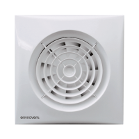
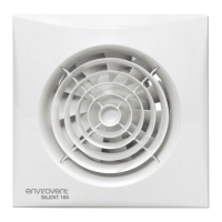
Window Model (Fig. 5)
These models have been designed for installation on a window (single or double glazed)
using the CLASSIC 100 Window Fixing Kit.
Fig.5 1 & 10
– Protection grille
2 – Cable entry point
3 – Connection cover
4 – Fixing screw
5 – Connection terminals
6 – Outlet
7 – Rubber joints
8 – Spacers
9 – Threaded ring
Cut a 105mm -diameter hole in glass.
Loosen the screws on the front and back protections grilles (1 and 10). Loosen the
threaded ring (9) and remove the 4 spacers (8).
Mount the fan depending on the installation requirements so that the glass is between
the two rubber joints (7):
Fig. 6a: All the spacers on the outside
Fig. 6b: All the spacers on the inside
Fig. 6c: Spacers on the outside an d the inside.
For double-glazing, one or more spacers m ay be discarded.
Fix the threaded ring. Fix the exterior grille in position, using the screws provided. This
fan must be installed by a c ompetent person. Complete electrical wiring of fan as
outlined in the Wiring Instructions overleaf. Then refit the front grille and tighten the
screw (2).
WIRING INSTRUCTIONS
IMPORTANT: ENSURE THAT THE MAINS SUPPLY IS SWITCHED OFF BEFORE
MAKING ELECTRICAL CONNECTIONS.
The CLASSIC
-100 is designed for single-phase supply, suitable for connection to 220 -
240V/1/50Hz supply. It is double insulated (Class II) and must not be earthed . The in-
stallation must include a double pole switch with a contact clearance of at least 3mm.
There are two options for cable entry to the fan. If using recessed wiring, the cable must
be introduced through the slot (7) (Fig. 1). If using surface wiring the cable must be intro-
duced as shown in Fig 3 and the break
-out region on the left hand side of the front grille
should be removed.
For access to the fan terminals, remove the safety cover screws and hinge up (Fig. 4).
•
•
•
•
•
•
•