EasyManua.ls Logo

Envirovent MEV 160 - User Manual

Envirovent MEV 160
19 pages
Print Icon
To Next Page IconTo Next Page
Loading...
MEV 160 & MEV 300
INSTALLATION GUIDE
AFTER INSTALLATION THE END USER SHOULD
KEEP THIS GUIDE FOR FUTURE REFERENCE
DO NOT THROW AWAY
Question and Answer IconNeed help?

Do you have a question about the Envirovent MEV 160 and is the answer not in the manual?

Summary

Safety and User Information

Safety Precautions

Read and understand installation instructions before starting. Unit must be installed by a competent person.

User Guidelines

Unit not for use by persons with reduced capabilities; supervision required. Children must not play with or clean the unit.

Electrical Connection Requirements

Wiring must comply with regulations. Unit requires continuous power, earthing, and a double pole switch for isolation.

Diagrams and Visuals

Wiring Diagram

Illustrates mains supply connection, local isolator, ventilation unit, and switch live options.

Unit Dimensions

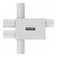
Provides detailed measurements for the unit and spigot connections.

Internal Access for Maintenance

Instructions on how to access the unit's interior for cleaning and maintenance.

Control Panel Layout

Diagram showing the control panel buttons and indicator LEDs.

Product Overview

MEV 160 & MEV 300 Features

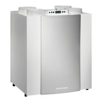
Continuous mechanical extract ventilation systems for fresh, healthy living environments.

Intellitrac Humidity Tracking

Monitors humidity and automatically adjusts airflow rate based on rising levels.

Boost Functionality

Units feature a switch live function to engage boost mode.

Installation Preparation

Box Contents

Lists all items included in the product packaging.

Pre-Installation Checklist

Ensures the installation site and conditions are suitable before starting.

Installation Procedure

Mounting and Cover Removal

Steps for positioning the unit and removing the front cover.

Spigot Installation and Fixing

Guide to inserting spigots and securely fixing the unit to the mounting surface.

External Termination and Ducting

Instructions for fitting external extract terminations and connecting ductwork.

Electrical Connections and Commissioning Prep

Details on wiring the unit and preparing for commissioning.

Commissioning

Setting Boost and Trickle Flow Rates

Procedure to set and verify extract flow rates for boost and trickle modes.

Functional Modes and Controls

Humidity Function Operation

Explains how the unit's fan speed increases with detected humidity.

Wired Boost Switch Control

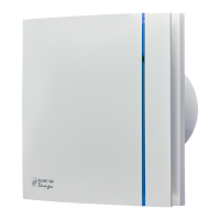
How to activate and deactivate boost mode using a hardwired switch.

Wireless Remote Control Operation

Instructions for manually activating boost and pairing remote controls.

Maintenance and Specifications

Remote Control Battery Replacement

Guide on how to replace the battery in the wireless remote control.

Technical Specifications

Details on extract spigot diameter, airflow rates, power consumption, and supply.

Air Flow Performance

Graph illustrating the unit's static pressure versus air flow rate.

Unit Cleaning

Instructions for cleaning the unit, including removing dust and debris.

Post-Installation Checklist

Items to verify after the unit has been installed.

Spares and Accessories

List of available spare parts and accessories with order codes.

Warranty Information

Details on the two-year warranty, conditions, and exclusions.

Overview

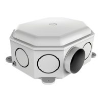
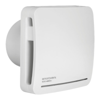
This document describes the EnviroVent MEV 160 & MEV 300, which are continuous mechanical extract ventilation systems designed to improve indoor air quality by removing humid, stale air from wet rooms and minimizing humidity transfer to other areas. These units are typically installed in a central location, with ductwork extending to the kitchen, bathroom, en-suite, utility, and other wet zones.

Function Description:

The MEV 160 and MEV 300 units operate continuously at a trickle airflow rate. They feature an Intellitrac® humidity tracking function that monitors humidity levels in the extracted air. When humidity rises, the airflow rate automatically increases to boost mode. Once humidity levels decrease, the system reverts to the programmed trickle setting. Both models include a switch live function, which, when engaged, activates boost mode. The units are available with either a wired boost switch or a wireless remote control for manual activation of the boost function.

Important Technical Specifications:

  • Model Variants: MEV 160 and MEV 300.
  • Airflow Capacity:
    • MEV 160: Maximum airflow of 75 l/s (270 m³/hr).
    • MEV 300: Maximum airflow of 103 l/s (370 m³/hr).
  • System Pressure:
    • MEV 160: Maximum system pressure of 573Pa.
    • MEV 300: Maximum system pressure of 650Pa.
  • Power Consumption:
    • MEV 160: Maximum 43.5W.
    • MEV 300: Maximum 69.5W.
  • Electrical Supply: 230V Single Phase 50Hz.
  • Ingress Protection Rating: IPX2.
  • Spigot Diameter:
    • Extract: 125mm or 75/90mm Fast Track.
    • Exhaust: 125mm.
  • Weight:
    • Boxed: 6kg.
    • Unboxed: 5kg.
  • Dimensions:
    • Length: 480mm.
    • Width: 340mm.
    • Height: 161mm.
  • Spigot Positions: The unit offers six possible spigot positions for extracting air from multiple locations. Up to three spigots are included, with additional spigot packs available for purchase if more are needed (up to a maximum of six).

Usage Features:

  • Installation: The unit should be installed by a competent person in a location with sufficient space for access and future servicing. It must not interfere with open-flue appliances. Ductwork should be rigid where possible, with a short length of flexible duct (300mm) for final connections. Ductwork in unheated spaces must be insulated.
  • Electrical Connection: Requires a continuous electrical power supply and must be earthed. Connection to fixed wiring should be made outside the unit. A double pole switch with a minimum contact separation of 3.0mm is required for isolation. The supplied flexible power cable must be used.
  • Commissioning: All building works must be complete before commissioning. Commissioning involves determining required ventilation rates, adjusting airflow settings (boost and trickle) using the control panel, and locking extract valves. The control panel is accessed by unclipping a cap with a flat-head screwdriver.
  • Control Panel: Features buttons for '+' and '-' adjustments and a 'SET' button. LEDs indicate the current mode: 'A' for Boost, 'B' for Trickle, 'C' for Humidity, and 'D' for Fault.
  • Hardwired Boost Switch (Standard Units): A black 2-core cable labeled "volt free input" connects to a hardwired boost switch. Moving the switch to the 'on' position activates boost mode; moving it to 'off' returns the unit to normal running mode.
  • Wireless Remote Control (Wireless Units): Pressing the button on the remote activates boost mode for 20 minutes, indicated by a green LED. Boost mode cannot be cancelled if a switch live connection is active until the switch live is turned off.
  • Remote Control Pairing: To pair an additional remote, turn the unit off at the isolation point, then restore power. Within 20 seconds of restarting, press the button on the new remote once. A green LED will light up if pairing is successful.
  • Remote Control Battery Replacement: Requires 1x CR2032 battery. Undo two screws, remove the rear casing, replace the battery (observing polarity), and reassemble. The switch remains paired after battery replacement.

Maintenance Features:

  • Cleaning: No maintenance is required other than cleaning during the two-year warranty period.
  • Access for Cleaning: To clean the unit, isolate it from the mains power supply. Undo the four screws around the front cover, use a flat-head screwdriver to lift the three clips along the edge, and gently pull the cover away. Remove any dust and debris from inside the unit.
  • Extract Valve Filters: Periodically remove dust and debris from any extract valve filters to prevent blockages.
  • Warranty: The unit is covered by a 2-year warranty. Tampering with internal components (beyond instructed cleaning) will void the warranty. Regular checks of valves are recommended to ensure airflow. For supply and installation by EnviroVent, a parts and labor warranty applies. For supply only, a parts-only warranty applies, provided installation was done by a competent person according to instructions. A receipt is required for proof of purchase.

Envirovent MEV 160 Specifications

General IconGeneral
BrandEnvirovent
ModelMEV 160
CategoryFan
LanguageEnglish

Related product manuals