2
AFTER INSTALLING THIS UNIT,
PLEASE PASS ONTO END USER
DO NOT THROW AWAY
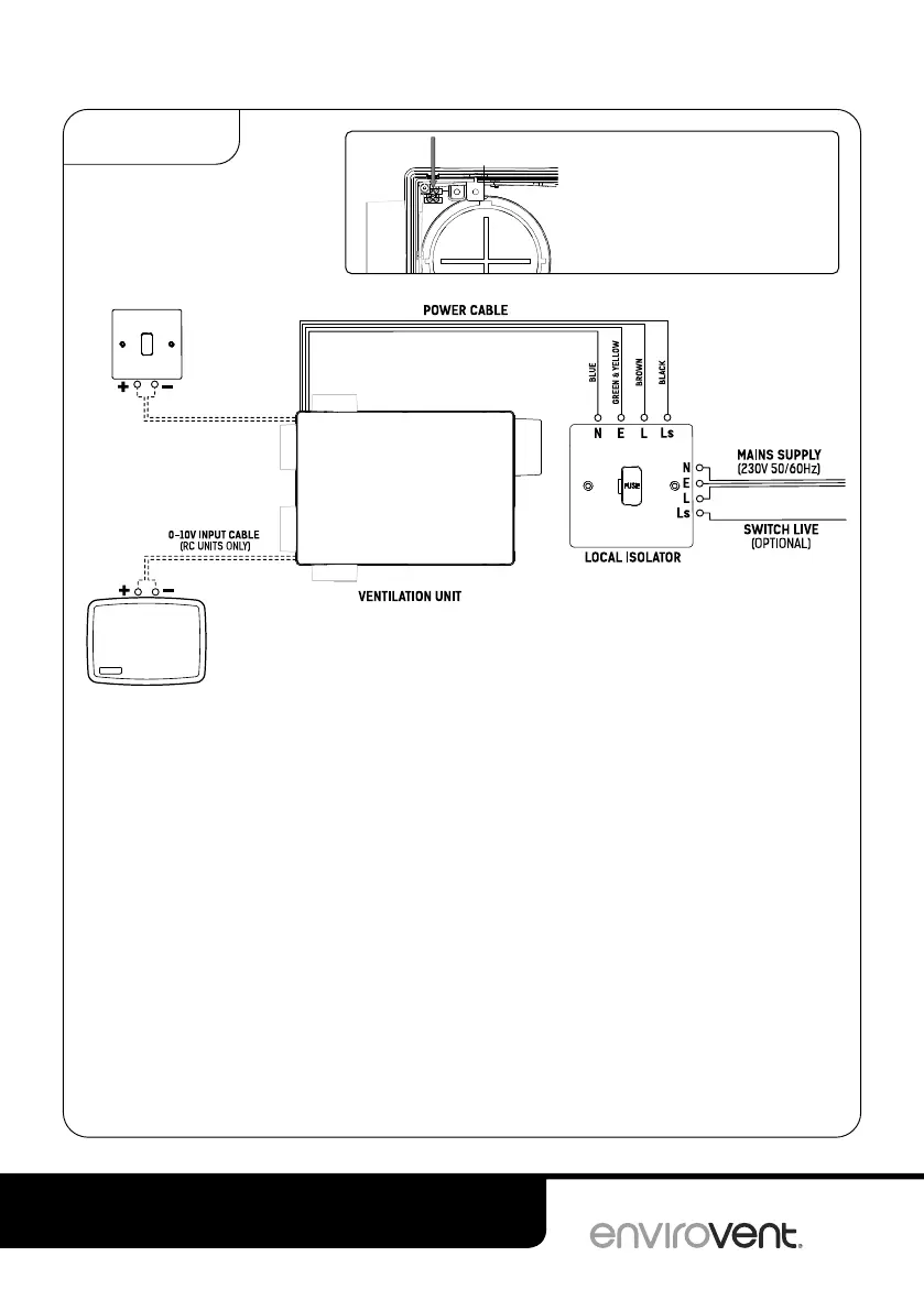
WIRING DIAGRAM
The local isolator must be connected to the mains as part of the fixed wiring. Connect the
cores of the power cable to the matching terminals on the local isolator (3A fuse spur or
similar).
The black switch live core of the mains cable can be wired to a switch input such as a room
light switch, when the switch is turned on, the boost function is engaged. When the switch
is turned off, the unit will turn to normal running mode. In this configuration a suitable triple
pole isolator must be used in line with the local wiring.
Standard units can be connected to the supplied hard wired boost switch via the black two
core cable labelled “volt free input”. See installation step 12.
Wireless units can be connected to a 0-10V input device via the terminal block at the end
of the black cable inside the unit. See installation step 11.
Do not connect the black boost switch cable or the black 0-10V input cables to the
mains power supply.
DIAGRAMS
VOLT FREE INPUT
(STANDARD UNITS ONLY)
HARDWIRED
BOOST SWITCH
(STANDARD UNITS ONLY)
0-10V CONTROL
INPUT DEVICE
(OPTIONAL)
BOOST
(RED) (BLACK)
(RED) (BLACK)
Cable block location
for 0-10V input.