4
INSTALLATION INSTRUCTIONS
Fig.4
Fig.2
Fig.1
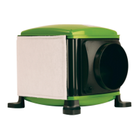
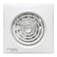
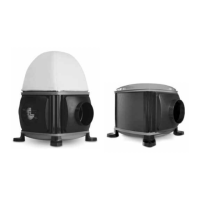
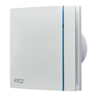
1. Loosen the two plastic screws and remove front
cover. (Fig 1.)
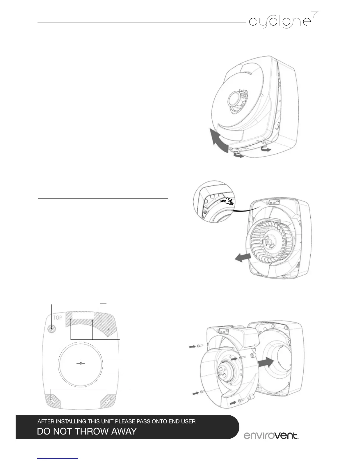
2. Carefully withdraw central cartridge from
the carcass. Disconnect green male/female
connector. (Fig 2.)
3. Drill Ø107mm hole in chosen position ensuring
clearance around fan. Insert ducting to suit (not
supplied).
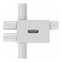
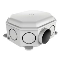
4. Use back carcass as a template, mark xing
holes, drill, plug and screw back carcass with
screws provided (4x 8x”1.5”). Fit the 3 blanking
plugs into holes in top chamber. (Fig 3.)
5. Please note that a suitable isolation switch or
fuse spur rated at 3amp should be used in the
xed wiring.
SELV Version (if installing 230V please see page 5)
6. This fan must be installed by a competent person.
Complete electrical wiring of fan. Tighten cable
gland. Low voltage requires connection via
power supply provided. Ensure red to red and
check mains connection in fused spur (3amp
fuse only).
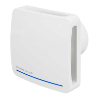
7. Oer up the central cartridge join green male/
female connector (12V DC) and carefully insert
central cartridge into back carcass. Insert four silver
screws to x central cartridge in place. N.B. Take
care not to trap cables. (Fig 4.)
Alternative xings
(blansk to be used)
100mm ducting (Ø106)
125mm ducting (Ø131)
Wall xings
Cable gland
NO CABLES
Avoid cable entry
into shaded areas
Fig.3