INSTALLATION INSTRUCTIONS
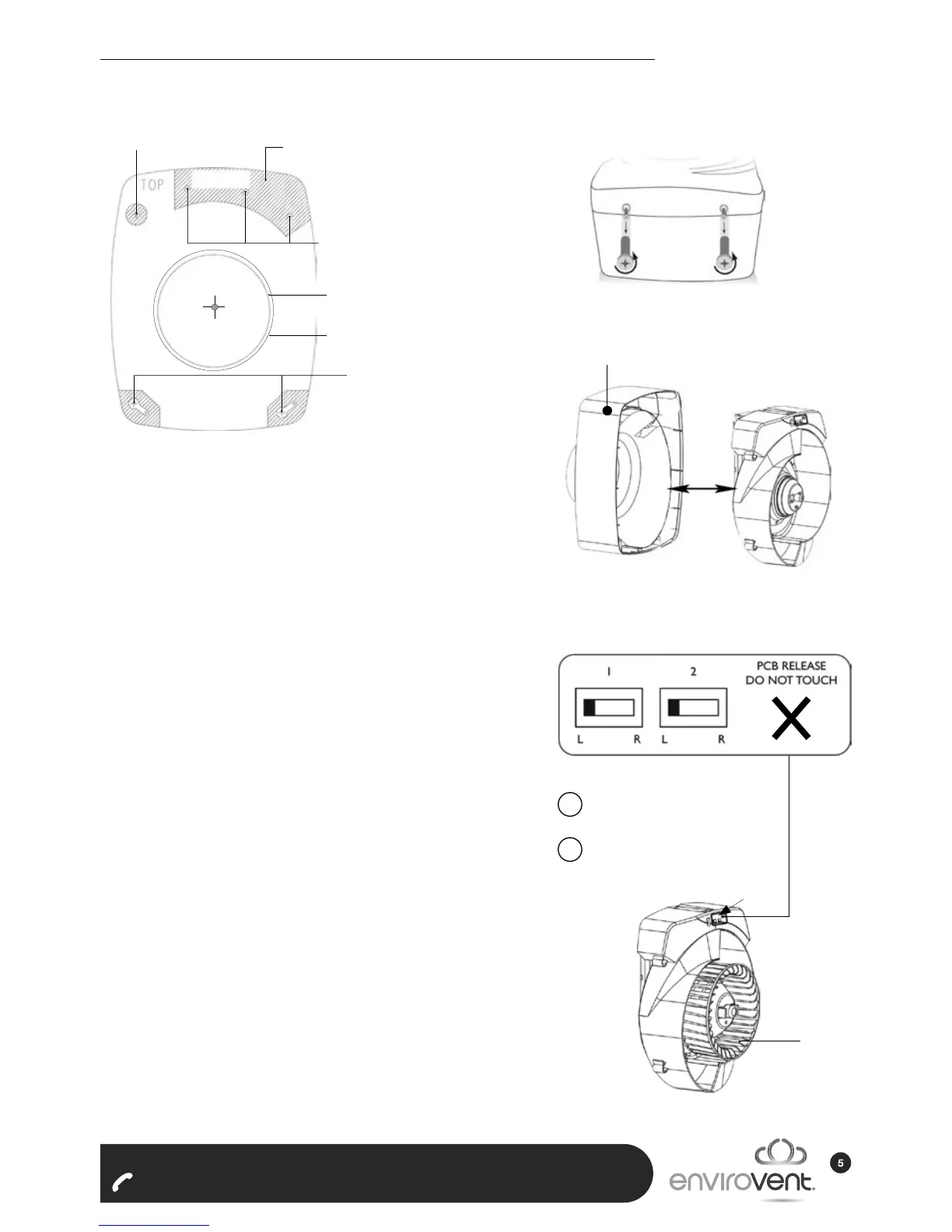
Fig.3
Fig.2
Fig.1
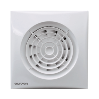
1. Loosen the two plastic screws and remove
front cover. (Fig 1.)
2. Carefully withdraw central cartridge from
the carcass. Disconnect green male/female
connector. (Fig 2.)
3. This fan must be installed by a competent
person. Complete electrical wiring of fan and
tighten cable gland.
4. Oer up the central cartridge, join green male/
female connector (230V) and carefully insert
the central cartridge into back carcass.
5. Insert four silver screws to x central cartridge
in place. N.B. Take care not to trap cables.
6. Please note that a suitable isolation switch or
fuse spur rated at 3amp should be used in the
xed wiring.
7. This fan is factory set to kitchen duty with
humidity tracking function. If two speed or
bathroom option is required, commission the
fan by setting the slider switch as appropriate.
Fix supplied gasket over selector switches
(Fig.3).
8. Check that the impeller is tted correctly -
ensure ‘click’ action engaged cleanly.
9. Fix front cover (Fig.1). Ensure that the pullcord
nestles into groove. N.B. Fan will not operate
unless front cover is in position.
10. This fan is factory set to kitchen duty with
humidity tracking function (Fig.3)
Alternative xings
100mm ducting (Ø106)
125mm ducting (Ø131)
Wall xings
NOT TO SCALE - FOR GENERAL INFORMATION ONLY
Cable gland
NO CABLES
Avoid cable entry
into shaded areas
Cable gland
Back carcass Central carcass
SLIDER
230V
Impeller
Gasket
LEFT - HUMIDITY TRACKING
RIGHT - TWO SPEED
1
LEFT - KITCHEN
RIGHT - BATHROOM
2