56
GA0383P02 Rev. C
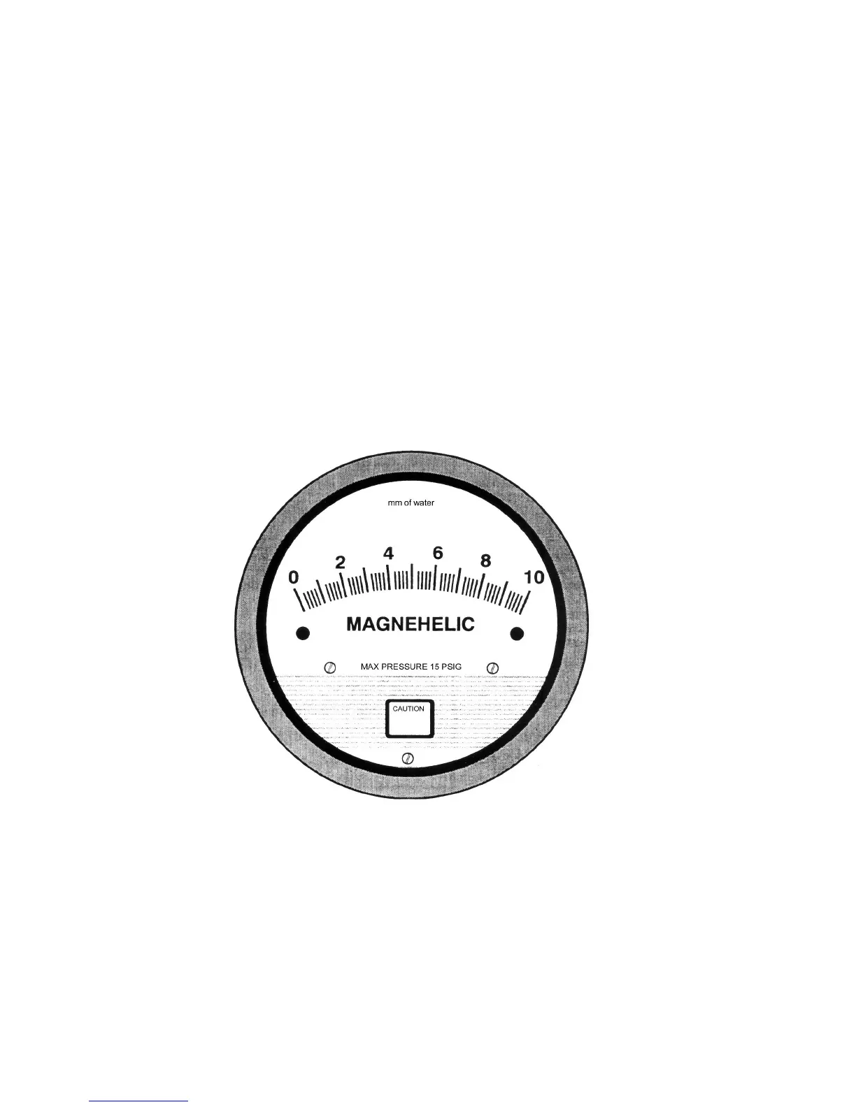
Figure 18 - Manifold DP Gage
Instruction Procedure:
1. Place gage on a level surface and check zero. Adjust if necessary, using the adjustment
on the front of the gage.
2. To check flow, remove the caps from the flow differential pressure taps on the manifold.
Connect the + tube (high side) to the + flow differential pressure tap, and the – tube to
the – flow differential pressure tap. (Refer to Figure 4, 5 or 6 of the IFD Samples System
Manual for tap locations on the manifolds.)
3. To check filter differential pressure, connect the gage to the respective + and – filter
differential pressure taps. Always replace caps on unused taps.
From FA0239P01 Rev. A, Appendix A for Manifold Differential Pressure (DP) Gage, Catalog No. FC0041G01