Do you have a question about the Epilog Laser Helix and is the answer not in the manual?
Unplug the machine, remove side panels, and center the X-beam for access.
Remove the X-beam cover and loosen the pulley tensioning system to slacken the belt.
Remove screws from lens assembly plates and pull belt ends free.
Lift the motor from its bracket after unscrewing captive screws.
Connect belt to lens assembly and route it around motor pulleys and spindles.
Re-secure the motor and position the belt correctly relative to cables.
Tension the belt, replace the X-beam cover, and reattach the side panels.
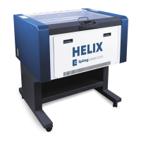
This document outlines the procedure for replacing the X-beam belt on a Helix laser machine. The X-beam belt is a critical component responsible for controlling the side-to-side movement of the laser head, ensuring precise operation during engraving and cutting tasks. The replacement process involves several steps, from initial preparation to the final reassembly and testing, designed to guide a user through the task effectively.
The Epilog Laser Helix machine utilizes an X-beam belt system to facilitate the lateral movement of the laser head. This belt, driven by a motor, translates rotational motion into linear motion, allowing the laser head to traverse the work area accurately along the X-axis. The integrity and proper tension of this belt are paramount for maintaining the machine's precision and the quality of its output. A worn, stretched, or damaged belt can lead to inaccuracies in engraving, misalignment of cuts, and overall degradation of machine performance. Therefore, timely replacement of the X-beam belt is essential for ensuring the continued high-quality operation of the Helix laser system. The belt's design, with its internal grooves, interfaces with corresponding pulleys and spindles to create a smooth and controlled movement, minimizing backlash and maximizing positional accuracy. The system is engineered to provide reliable and repeatable motion, which is a cornerstone of precise laser processing.
The Helix laser machine, while sophisticated in its capabilities, is designed with user maintenance in mind, particularly for components like the X-beam belt. The replacement procedure begins with fundamental safety precautions, such as unplugging the power cord, to prevent accidental activation during maintenance. Access to the X-beam belt system is facilitated by removable side panels and an X-beam cover, which are secured with Philips head screws. This design allows for relatively straightforward access to the internal mechanisms.
The process of slackening the belt involves manipulating a pulley tensioning system located on the left side of the X-beam. This system uses two screws that, when loosened, allow a black pulley to be pressed inward, thereby reducing the tension on the belt. This feature is crucial for both removing the old belt and installing the new one without excessive force or damage to the components. The lens assembly, which is directly connected to the belt, also features a removable plate secured by four screws, enabling the detachment of the belt ends. This modular design simplifies the process of isolating and replacing the belt without requiring extensive disassembly of the entire laser head mechanism.
Re-installing the belt, while described as "tricky," emphasizes the importance of careful routing around the various pulleys and spindles. On the right side of the X-beam, the belt must navigate around two pulleys, and its grooves must face the inside of the machine to ensure proper engagement. The motor, which drives the belt, is secured by three captive screws, allowing it to be lifted out of its bracket. This provides necessary clearance for looping the belt around the black pulley inside the motor bracket and the silver spindle connected to the motor. The captive screws are a thoughtful design element, preventing loss of fasteners during maintenance.
The final steps of belt installation involve re-tensioning the belt. This is achieved by loosening two pulley screws on the left side of the X-beam, allowing the pulley to snap into place and apply the correct tension. This self-tensioning mechanism, combined with a gentle pull on the pulley assembly, helps ensure that the belt is neither too loose nor too tight, both of which can negatively impact performance and belt longevity. The reassembly of the X-beam cover and side panels concludes the physical maintenance, returning the machine to an operational state. The design considerations throughout this process aim to balance the complexity of internal mechanisms with the need for user-friendly maintenance, enabling technicians or experienced users to perform necessary repairs and upkeep.
The maintenance procedure for the X-beam belt on the Helix machine highlights several key features designed to facilitate servicing and ensure the longevity of the device. The use of standard tools, specifically a Philips head screwdriver and needle-nose pliers, means that specialized equipment is not required, making maintenance accessible. The step-by-step instructions, including visual aids (though not explicitly described, the context implies their presence in a full manual), guide the user through each stage of the replacement, minimizing the chance of error.
The design of the X-beam cover, secured by a combination of front and back screws, allows for partial loosening rather than full removal, streamlining the access process. This detail reduces the number of loose parts and simplifies reassembly. The pulley tensioning system is a critical maintenance feature, enabling precise adjustment of belt tension. The ability to loosen screws, press a pulley, and then re-tighten ensures that the belt can be properly slackened for removal and then accurately tensioned for optimal performance. This adjustability is vital for compensating for minor belt stretch over time and for achieving the correct tension after a new belt is installed, which directly impacts the accuracy and smoothness of the laser head's movement.
The motor's attachment with captive screws is another thoughtful maintenance feature. Captive screws remain attached to the component even when loosened, preventing them from being misplaced during the removal and reinstallation of the motor. This small detail significantly improves the efficiency and ease of maintenance, especially in environments where small parts can be easily lost. The routing of the belt, particularly the instruction to pull it behind the X-beam but in front of the white ribbon cable, demonstrates an awareness of potential interference with other critical components. This guidance helps prevent damage to delicate cables and ensures proper clearance for the belt's movement.
The final tensioning step, where the pulley "snaps into place," suggests a design that assists in achieving the correct tension without requiring specialized tension-measuring tools. This feature simplifies the process for users, allowing for a more consistent and reliable tensioning outcome. The emphasis on replacing the X-beam cover and side panels at the end of the procedure underscores the importance of maintaining the machine's protective enclosure, which shields internal components from dust and debris, thereby contributing to the overall longevity and reliability of the Helix laser system. The availability of technical support contact information further reinforces the commitment to user assistance, providing a resource for troubleshooting or clarification during maintenance tasks.
| Laser Type | CO2 |
|---|---|
| Resolution | up to 1200 dpi |
| Cooling System | Air-cooled |
| Software | Epilog Dashboard |
| Warranty | 2 years |
| Laser Power | 30, 40, 50, 60 watts |
| Max Material Thickness | 8" (203 mm) |
| Connectivity | USB |
| Operating System Compatibility | Windows |
| Operating Modes | Raster, Vector, Combined |
| Power Supply | 50/60Hz |
| Supported File Formats | AI, EPS, PDF, DXF, BMP, GIF, JPEG, PNG, TIFF |
| Work Area | 24" x 18" (610 x 457 mm) |