EasyManua.ls Logo

Epilog Laser Zing User Manual

Epilog Laser Zing
12 pages
To Next Page IconTo Next Page
Page #1 background imageLoading...
Page #1 background image
Replacing Backplane Board on a Zing
1. Disconnect the machine from its power source.
2. Remove the power cord from the machine.
3. Loosen the captive screws shown in picture 1
Picture 1
4. Remove the control/display assembly from the machine by grasping the
captive screws and pulling the control board/display assembly toward you
as shown in picture 2.
Question and Answer IconNeed help?

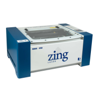
Do you have a question about the Epilog Laser Zing and is the answer not in the manual?

Epilog Laser Zing Specifications

General IconGeneral
BrandEpilog Laser
ModelZing
CategoryEngraver
LanguageEnglish

Summary

Backplane Board Replacement Procedure

Initial Disconnection and Control Panel Removal

Disconnect power, remove cord, loosen captive screws, and detach the control/display assembly.

Removing Control Panel Screws

Unscrew the three indicated screws from the control panel.

Side Cover Removal

Lift the bottom of the right side cover, pull it forward, and then lift it away.

Cable Disconnection

Unplug all necessary cables from the component.

Motherboard Housing Bolt Removal

Remove the bolt securing the motherboard aluminum housing with a 5/32 wrench.

Component Securing Screw Removal

Unscrew the five screws that hold a component in place.

Backplane Board Fastener Removal

Remove the three screws that secure the backplane board.

Secondary Board Screw Removal

Unscrew the two additional screws holding the board.

Post Removal

Remove two posts using a 7/32 Allen wrench.

Final Board Connections Release

Release Allen wrenches from a plastic connector and unplug board connectors.

New Backplane Board Installation

Install the new backplane board by reversing the disassembly steps 1 through 13.

Related product manuals