Do you have a question about the Episode E-2100 and is the answer not in the manual?
Combines the power output of both channels for increased power when needed.
Offers 'On', 'Auto', and 'Trigger' modes for flexible amplifier power control.
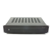
Initial setup guidance including amplifier placement, ventilation, and basic connections.
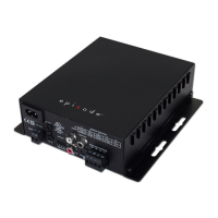
Covers input selection, power connection methods, and channel bridging configuration.
Addresses issues with no audio output across all channels.
Helps diagnose problems affecting specific audio channels.
Guides on resolving audio issues affecting a single channel or zone.
Provides steps to identify and eliminate hum or buzzing audio artifacts.
Offers solutions for the amplifier failing to power on.
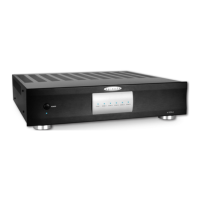
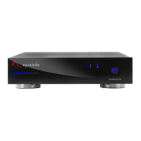
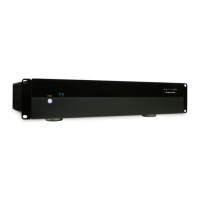
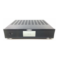
This document is the owner's manual for the Episode E-2100 Stereo Power Amplifier, engineered by SnapAV.
The Episode E-2100 is a 2-channel stereo power amplifier designed for various amplifier applications in home theater or audio systems. It incorporates advanced technology components to deliver high-quality sound for both movies and music. The amplifier is built with superior quality components for outstanding sound quality, performance, and long-term reliability.
The manual provides a troubleshooting guide for common issues: