Do you have a question about the Episode ESA-70V2CH-150W and is the answer not in the manual?
Highlights crucial electrical safety, including plug, cord, and shock prevention measures.
Explains the function and status indicators of the power button.
Describes the protection LED's role in indicating operational status or issues.
Details the output level meter's function and color-coded indicators for signal levels.
Explains setting input voltage for 115V/230VAC and fuse considerations.
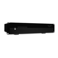
Details attaching rack ears, securing the unit, and required air space.
Explains the power button function and its LED color indicators.
Step-by-step guide to calibrate source input and inline volume levels.
Details power output, sensitivity, impedance, frequency response, and fuse types.
Addresses problems like no power, red LED, hum, or no audio from speakers.
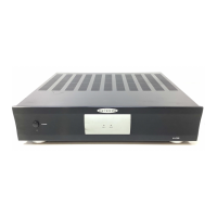
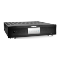
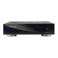
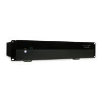
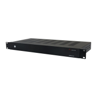
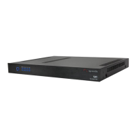
The Episode ESA-70V2CH series of digital power amplifiers is designed for applications requiring two-channel stereo audio or two mono zones of audio with different sources or levels. These amplifiers offer low heat output due to digital amplification and deliver substantial power in a compact 1U or 2U package.
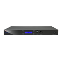
The amplifier features a front panel with a Power Switch with LED Indicator, a Protection LED, and an Output Level Meter. The Power Switch is a momentary switch for manual control of the standby power mode; it illuminates blue when on and red when in standby. The Protection LED indicates whether a channel is operating correctly (blue) or is in protection mode (red), signaling a potential issue with installation or setup. The Output Level Meter flashes green to indicate the current output level for each channel, with LEDs illuminating green for levels ranging from -30dB to -10dB. If a channel is clipping, the red CLIP LED will illuminate, indicating that the input level should be reduced immediately.
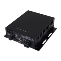
The rear panel provides a comprehensive set of connections and controls. An Ethernet Port (RJ45) allows for IP control of the amplifier using a Cat5e/6 cable. An IR port accepts a mono connector (signal and ground only, no 12V signal supplied) for controlling the amplifier via IR from a control system. An RS-232 port facilitates communication with a control system or PC for serial control. Dry Contact inputs can be used to toggle the amplifier ON/OFF or mute/unmute, configurable through the web GUI.
For external control and daisy-chaining, the amplifier includes 12 Volt Trigger IN and OUT ports. When 4.5-15 Volts DC are applied to 12V IN, the amplifier turns on, and when the voltage drops, it turns off. The 12V OUT port allows other equipment to be controlled by the same 12V signal.
Audio input and output options include Loop Outputs 1 & 2, which are unbalanced mono RCA connections for sending audio to other devices. Unbalanced Inputs 1 & 2 are unbalanced mono RCA input connections for connecting sources. Balanced Inputs 3 & 4 are set-screw connections for sources with balanced output. Input Level Adjustment Dials, which are digital encoders, allow for adjusting input volume levels by turning clockwise to increase and counter-clockwise to decrease volume.
Speaker Output Connections are set-screw terminals for speaker output channels 1 & 2, accommodating 22-14AWG wire. The amplifier is powered via an IEC Power Cord, which is detachable. A replaceable AC Fuse provides main power protection.
On the bottom panel, an Input Voltage Switch allows setting the input voltage for 115V or 230VAC operation based on the available voltage.
The ESA-70V2CH amplifier is designed exclusively for use with 70V loudspeakers. Users can combine any speakers as long as the sum of their wattage does not exceed the rated wattage of the speaker output.
For balanced input connections, the amplifier can connect to balanced or unbalanced cables. An adapter can be created by jumping between Shield and Negative(-) if there is no balanced source and more unbalanced source connections are needed. Unbalanced connections use standard RCA cables for sources, with LOOP OUT ports available to connect additional amplifiers or equipment. The LOOP OUT connections send audio signals from the UNBALANCED INPUT of the channel to other equipment or to another channel of the amplifier.
Control connections include IR, RS-232, and IP. The IR input accepts a mono connector for control from a control system. The RS-232 port allows serial control, receiving data on pin 2 (RxD) and transmitting on pin 3 (TxD). For IP control, a Cat5e/6 network cable connects the amplifier to a DHCP-enabled network. An IP scanner can detect the assigned IP address, which can then be entered into a web browser to access the user interface. Default login credentials are "admin" for both username and password. The web GUI allows configuration of System Status, Power On settings, Input/Output configuration, Network IP and Clock settings, Audio Routing configuration, and Password settings.
The amplifier's power control includes a Front Panel Power Button for manual standby control. The 12 Volt Trigger function allows for trigger control and daisy-chaining multiple amplifiers using mono mini cables. Audio Sense, if enabled via the web GUI, allows the amplifier to turn on when an audio signal is detected and enter standby mode after 15 minutes of no signal.
Volume calibration is a critical setup step. This involves connecting all wiring, setting volume controls to maximum, setting input level knobs to 50% (and unused channels to minimum), playing typical audio with the source volume at half, and adjusting the level for the area to a slightly above normal listening level. Fine-tuning gain settings can be done through the web GUI.
Troubleshooting guidance is provided for common issues. If the amplifier does not turn on, users should check power cable connections, verify power at the outlet, and inspect the main power fuse, ensuring the AC voltage switch is correctly set. If the POWER LED is red, the amplifier may be in protection mode due to excessive current draw, overheating, or an incorrect load calculation. Users should verify wiring, calculate the load, and allow the amplifier to cool if overheating is suspected.
For hum or buzzing sounds, RCA input cables should be checked by removing them one at a time. If there is no audio from speakers, users should verify speaker and wiring connections, use the OUTPUT test tone function in the web GUI, check source operation and input wiring, and ensure the Power LED is not red. If the CLIP LED illuminates, the input volume should be reduced to prevent pushing too much power to the speakers.
The device is covered by a 2-Year Limited Warranty, which includes parts and labor for defects in material or workmanship under normal use. The warranty does not cover products that have been abused, modified, or disassembled. For warranty repairs, products must be returned to a designated service center with an assigned return authorization (RA) number. Technical support is available via phone and email.
| Power Output | 150W |
|---|---|
| Channels | 2 |
| Impedance | 4-8 Ohms |
| Frequency Response | 20Hz - 20kHz |
| Total Harmonic Distortion (THD) | <0.1% |
| Signal-to-Noise Ratio | >90dB |
| Input Impedance | 10k Ohms |
| Cooling | Convection |
| Input Sensitivity | 0.775V (0dBu) |