EasyManua.ls Logo

Episode EA-AMP-HYB-2D-1000 - User Manual

Episode EA-AMP-HYB-2D-1000
20 pages
Print Icon
To Next Page IconTo Next Page
Loading...
PRODUCT MANUAL
EA-AMP-HYB-2D-1000
EA-AMP-HYB-2D-2000
EA-AMP-HYB-2D-1000
CH.SEL
PROTECT
CH2
ADJUST | SET
MENU
BACK
CLIP
-10
-20
SIGNAL
PROTECT
CH1
CLIP
-10
-20
SIGNAL
A
T
TENTION ! RISQUE DE CHOC ! ÉLECTRIQUE P
AS OUVRIR !
CAUTION
RISK OF ELECTRICAL SHOCK!
DO NOT OPEN!
!
Use only a 250V fuse
Employer uniquement aux
un fusible de 250V
U
C UL
LIFTED
ON
OFF
110 V FUSE T8AH 250V
230V FUSE T4A H250V
118V110-120V AC-60H-230W
230V230-240AC-50Hz-230W
SPEAKER OUT
BRIDGE
DIGITAL
IN
CH1
CH1
CH2
CH2
LINE OUT
CH1
CH1
CH2
CH2
IN
LINK ACT
OUT
LINE IN
TRIGGER
DC 12 V
SERIAL
CONTROL
NETWORK
CONTROL
OUT
CH2 CH1
L

Other manuals for Episode EA-AMP-HYB-2D-1000

Questions and Answers

Summary

Important Safety Instructions

General Safety Precautions

Essential safety guidelines for operating the amplifier to prevent hazards.

Introduction

Product Overview

Thank you and overview of the Episode amplifier features.

IP;OvrC Control

OvrC Connection Setup

Connect amplifier to LAN for OvrC setup via www.OvrC.com.

Local UI Access

Access local user interface by entering the amplifier's IP address into a web browser.

Speaker Recommendation

Loudspeaker Compatibility

Guidance on compatible speaker types and impedance.

Front Panel Overview

Display Panel

Displays system information on the front panel.

Channel Select Button

Button to select the input channel on the amplifier.

Rear Panel Connections

Network and Serial Ports

Ethernet and RS-232 ports for control and communication.

Audio and Trigger Inputs;Outputs

12V Trigger, balanced/unbalanced audio inputs and loop outs.

Speaker Terminals and Power

Speaker connections, main power switch, IEC cord, and fuse.

Source Connections and GUI

Input Signal Routing

Connect sources via analog/digital inputs and line out.

Gain, Input Mode, and Delay Settings

Configure input mode, source, gain, and delay via GUI.

Input Gain and Volume Control

Optimizing Input Voltage for Performance

Adjust Input Gain to match source voltage for optimal amplifier output.

Volume Control Methodologies

Using amplifier or source output for volume control.

Speaker Connections and Output Modes

Wiring and Output Mode Selection

Connect speakers using appropriate wire and select output mode.

Bridge Mode Operation

Enable bridge mode for increased output power.

Amplifier Power Management

Power Button and Resetting

Front panel power control and amplifier reset procedures.

12 V Trigger and Audio Sense

12 V Trigger Functionality

Connect 12V DC for trigger control and daisy-chaining.

Audio Sense Operation

Amplifier auto-on via audio signal detection.

Volume Calibration Procedure

Calibration Steps

Detailed steps for calibrating source input gain and volume controls.

Device Setup and Calibration

Triad Matrix Volume Control Setup

Steps for calibrating volume with Triad Matrix.

Hybrid Amp Volume Control Setup

Steps for calibrating volume using the Hybrid amp.

Speaker Presets

Available Speaker Presets

Built-in presets for landscape speakers and subwoofers.

Preset Group B Configuration

Files for mixing LS-SAT models between channels.

Using Speaker Presets

Local Display Preset Selection

How to select and load presets using the front panel.

Web Interface Preset Selection

How to select and load presets via the web interface.

Preset File Management

Importing Preset Files

Steps to import new preset files into the amplifier.

Additional Preset Group B Files

Table for mixing LS-SAT models using Preset Group B.

Preset Group C Configuration

Preset Group C Table

Table for landscape speakers and subwoofers using Preset Group C.

Troubleshooting Common Issues

Amplifier Protection Mode

Scenarios and resolutions for protection mode activation.

No Audio Output Resolution

Troubleshooting steps for when there is no audio output.

Audio Quality Issues

Resolving Volume Distortion

Eliminate distortion by re-adjusting volume and gain levels.

Preventing Inline Volume Thumps

Calibrate inline volume controls to avoid "thumping" sounds.

Product Specifications

Channels and Power Output Details

Configuration and power output ratings.

Input and Impedance Specifications

Input sensitivity and impedance details.

Audio Performance Metrics

Signal-to-noise ratio and harmonic distortion levels.

Physical and Electrical Specs

Dimensions, voltage, power consumption, and certification.

Legal Notices and Warranty

Warranty Information

Details on limited warranty and legal notices.

Technical Support Contact

Support Contact Information

Phone number and email for technical support.

Overview

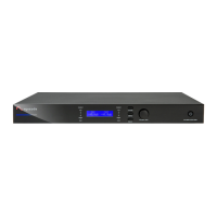
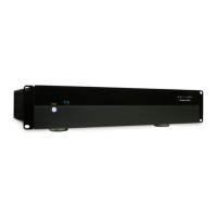
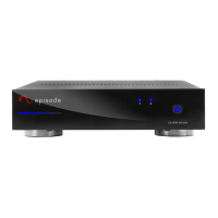
This document describes the Episode Hybrid Amplifier models EA-AMP-HYB-2D-1000 and EA-AMP-HYB-2D-2000, which are two-channel amplifiers designed for various audio applications.

Function Description

The Episode Hybrid Amplifier is a two-channel amplifier capable of operating with either 70V or 8 ohm loudspeakers, with selectable output modes for each channel. It supports two-channel stereo audio or two mono zones with different sources or levels. Channels can also be bridged to increase output power and send a singular mono signal. The amplifier is optimized for peak performance when the input voltage of the source is 1.4V, and includes a pre-amplified stage to modify the input source voltage if it is less than 1.4V.

Important Technical Specifications

Channels: 2-channel

Power Output:

  • 300W per channel @ 8 ohm (1000W bridged)
  • 500W per channel @ 4 ohm (2000W bridged)
  • 700W per channel @ 2 ohm
  • 500W per channel @ 70V
  • 500W per channel @ 100V (230V AC only)

Input Sensitivity: 1.4 Vrms, max power

Input Impedance:

  • RCA analog input: 10kΩ
  • Balanced analog input: 20k Ω

Signal-to-Noise Ratio: 101 dB A-weighted @ 1.4 Vms & 4Vms input max

Total Harmonic Distortion (THD): Less than 1%

Frequency Response: ± 2d B at 1/8 power (20 Hz to 20 kHz)

Inputs:

  • Network: RJ45 jack, 10/100 Mbps
  • Bal. Analog Audio: 2 × 3-post Phoenix-style pluggable screw terminal block
  • Analog RCA: White jack (L. ch), Red jack (R. ch)

Audio Inputs/Outputs:

  • Spkr. Output: 2 x 3 post Phoenix-style pluggable screw terminal block (12-18 AWG)

12 Volt Trigger: 3.5 mm mono jack

Dimensions (WxHxD): 431.8 mm (17") x 43.942 mm (1.73") x 355.6 mm (14")

Rack Spacing: 1U

Input Voltage: 115V AC / 230V AC

Weight: 5.44 kg (12 lb)

Certification: Meets FCC Part 15, UL EN60065

AC Power Consumption: 230W typical, 1100W max

Usage Features

IP/OvrC Control: The amplifier can be connected to a LAN for OvrC control. Users can create an account on www.OvrC.com, add the device using its MAC address and serial number, and follow setup directions. The local UI can also be accessed via a web browser by entering the amplifier's IP address (displayed on the front panel). Default login credentials are username: episode, password: episode.

Front Panel Controls:

  • Display Panel: Shows system information.
  • Channel Select: Press to select the input channel.
  • Menu Select: Press to cycle through system menus.
  • Back Button: Navigates back one step in the system menu.
  • Level Adjustment/Selection Knob: Turns to adjust system levels, presses to select.
  • Power Switch with LED Indicator: Momentary switch for manual control of standby power mode (Blue for On, Red for Standby).

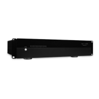
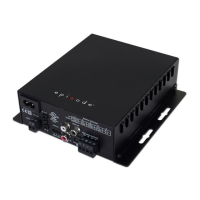
Rear Panel Connections:

  • Ethernet Port (RJ45): For IP control.
  • RS-232: For communication with a control system or PC.
  • 12V Trigger IN and OUT: Allows the amplifier to turn on/off with a 4.5-15V DC signal and control other equipment.
  • Balanced Inputs 1 & 2: Set-screw connections for balanced sources.
  • Unbalanced Inputs 1 & 2: RCA input connections for unbalanced sources.
  • Unbalanced Loop Out 1 & 2: RCA loop out for connecting to other amplifiers.
  • Balanced Loop Out 1 & 2: Set-screw balanced loop out for connecting to other amplifiers.
  • Digital Input/Output Ports: For digital sources.
  • Speaker Terminals: Screw terminals for speaker connections, with markings for bridge mode.
  • Main Power Switch: Main amplifier power switch.
  • IEC Power Cord: Detachable power cable.
  • AC Fuse: Replaceable main power fuse.

Speaker Connections and Output Mode: Use 14 or 16 gauge stranded two-conductor speaker wire. Connect to screw terminals, observing polarity. Bridged markings are provided. Burial-rated wire should be used for outdoor applications. Output mode (8 Ohm, 70V, 100V) can be configured via the web interface.

Amplifier Power Control:

  • 12V Trigger: Amplifier turns on when 4.5-15V DC is applied to 12V IN and turns off when voltage drops. 12V OUT allows daisy-chain control of other equipment.
  • Audio Sense: If enabled via the web interface, the amplifier turns on when an audio signal is detected and enters standby after 15 minutes of no signal.
  • Power State: Supports Deep vs. Light Sleep modes. Deep sleep is required for EU low power consumption standards when the amplifier is not operational (not enabled out of the box).

Volume Calibration: To calibrate source input gain and inline volume control:

  1. Connect all speakers and audio sources, then power on the amplifier.
  2. Set all volume controls to maximum (if applicable).
  3. Set each output level adjustment knob to 50% and unused input levels to minimum.
  4. Power on the amplifier and input source, play typical audio.
  5. Set source volume to half; if distorted, reduce until clear.
  6. Adjust the level for the area slightly above normal listening level; if distorted, adjust source volume and LEVEL knob until clear.

Speaker Presets: The amplifier comes with preloaded presets for various landscape speaker configurations, including full system presets and DSP settings for use with ES-LS-BSUB-12 or ES-LS-HSUB-10 subwoofers. Subwoofers must be connected to Channel 1 when using these presets. Additional preset files (Preset Group B and C) are available on the product's Support tab for mixing different LS-SAT models between channels or for use with ES-LS-BSUB-8 or ES-LS-BSUB-10.

Using Presets:

  • Local Display: Press Menu, rotate Adjust/Set to "Menu Preset", press, rotate to desired preset, press to load.
  • Web Interface: Click "Preset" button, select from drop-down list, click "Load Preset".
  • Loading Preset Files: Click "Import Preset", choose file, click "Load". Refresh the page for new presets. Loading a preset file erases current listings; "Reset Presets" restores defaults.

Maintenance Features

Resetting the Amplifier:

  • Soft Reset: Press and hold the BACK button for 10 seconds after power-on to reset login information.
  • Factory Reset: Press and hold the BACK button for 20 seconds to reset all settings including DSP, channel levels, and input names. Front panel lights will flash during the process.

Troubleshooting:

  • Going into Protection (Red Protect LED Blinking):
    • High Temperature: Allow unit to cool down.
    • High Current: Reduce input music level.
    • Firmware Updating: N/A, allow update to finish.
  • Going into Protection (Red Protect LED Solid):
    • Speaker Terminal Short: Ensure speaker terminal is fully connected. Remove speaker terminal; if light is still solid, investigate further.
    • Failure to Jump to Partition after Firmware Update: Contact Tech Support for firmware recovery.
  • No Output (Level Meter LEDs/WebUI):
    • Level Meter (Green LED) Illuminates: Ensure speaker output is configured correctly.
    • Level Meter in Web UI is Responsive: Ensure source inputs are configured correctly.

Distorted Audio at Normal Volume: If the LEVEL adjustment is too high for low source volume, distortion (background noise, clipping, etc.) can occur. Re-adjust volume levels starting at baseline settings, ensuring maximum comfortable volume without distortion using source volume or inline control.

Inline Volume "Thump": If a "thumping" sound is heard, amplifier and source volume levels are too high. Calibrate inline volume controls to be one or two adjustment levels away from maximum at normal listening level, allowing for extra volume if needed.

Episode EA-AMP-HYB-2D-1000 Specifications

General IconGeneral
BrandEpisode
ModelEA-AMP-HYB-2D-1000
CategoryAmplifier
LanguageEnglish

Related product manuals