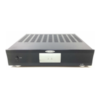
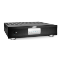
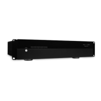
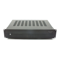
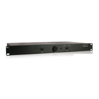
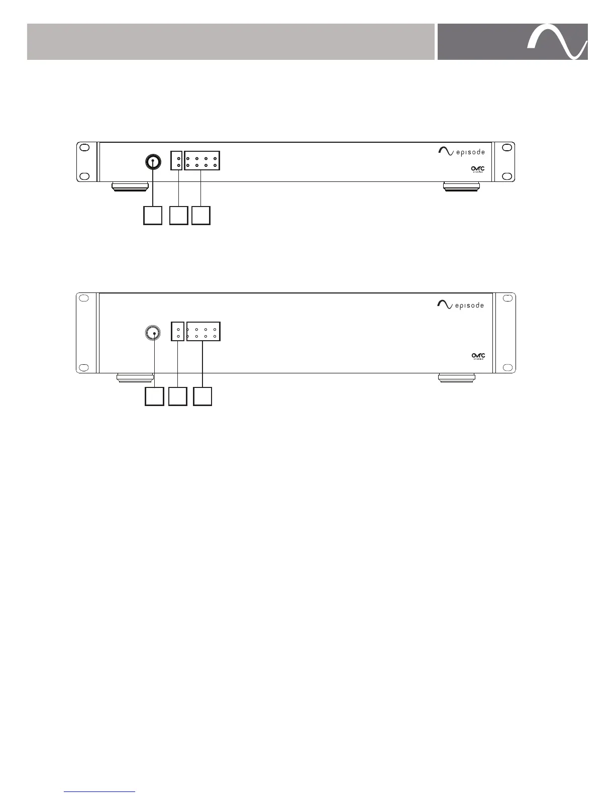
FRONT PANEL
ESA-70V2CH-150W, 300W
PROT -30 -20 -10 CLIP
1
2
ESA-70V2CH-IP-150W
ESA-70V2CH-500W
PROT -30 -20 -10 CLIP
1
2
ESA-70V2CH-IP-500W
A. Power Switch with LED Indicator
Momentary switch for manual control of standby power mode.
BLUE – On.
RED – Standby.
B. Protection LED
Indicates whether a channel is operating correctly or is in protection.
BLUE – Normal.
RED – Protection. (Indicates an issue with installation or setup)
C. Output Level Meter
Level meter flashes green to indicate current output level for each channel. LEDs will
illuminate green accordingly as levels ranging from -30dB to -10dB are played. If a
channel is clipping, the red CLIP LED will illuminate during periods of clipping (turn down
input level immediately if clipping occurs).
A B C
A B C
 Loading...