20
EE33 Humidity / Temperature Sensor for High Humidity and Chemical Applications
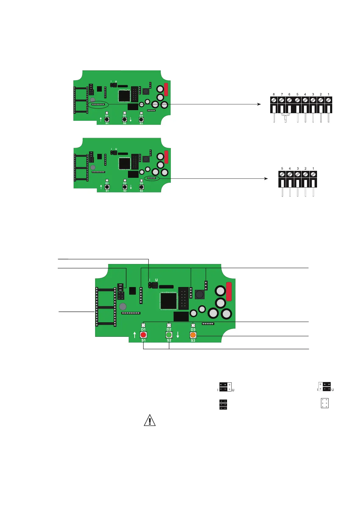
6.5 Connection Configuration of Connectable Sensing Probe (Option PC6)
9-pole terminal
∅12 mm (0.5") sensing probe:
grey
shielding
shielding (yellow/green)
grey (yellow/green)
brown
yellow
blue
black
pink
5-pole terminal
shielding
blue
grey
black
brown
∅6 mm (0.25")sensing probe:
7 Operating Components
7.1 Circuit Board
1. Current/voltage output: If the sensor will be switched from current to voltage output signals
using the configuration software, then two jumpers must also be
positioned as follows:
for current signal: for voltage signal:
2. RS232/RS485: jumper set - RS232: jumper removed - RS485:
3. Fitting of the network chip: For refitting to RS485, an IC must be used (available as option J3
or via accessory HA010605).
The notch on the chip must match the receiver slot!
4. Display: Pinboards for connecting the display module.
5. Diagnosis LEDS: refer to chapter 9 “Humidity / Temperature Calibration”
refer to chapter 10.4 “Self Diagnosis and Error Messages”
6. Push-button (heated measurement cell): refer to chapter 10.2 “Automatic ReCovery (ARC)”
7. Push-buttons (calibration): refer to chapter 9 “Humidity / Temperature Calibration”
After removal of the enclosure cover, the following operating components on the circuit board may be
accessed.
1. current/voltage output
4. display
5. diagnosis LEDs
7. push-buttons (calibration)
6. push-button (heated measurement cell)
2. RS232/RS485
3. fitting of the
network chip