Page 27
Direction for Use (GB) / Gebrauchsanleitung (D)
Converter CON 011
Figures / Abbildungen
0
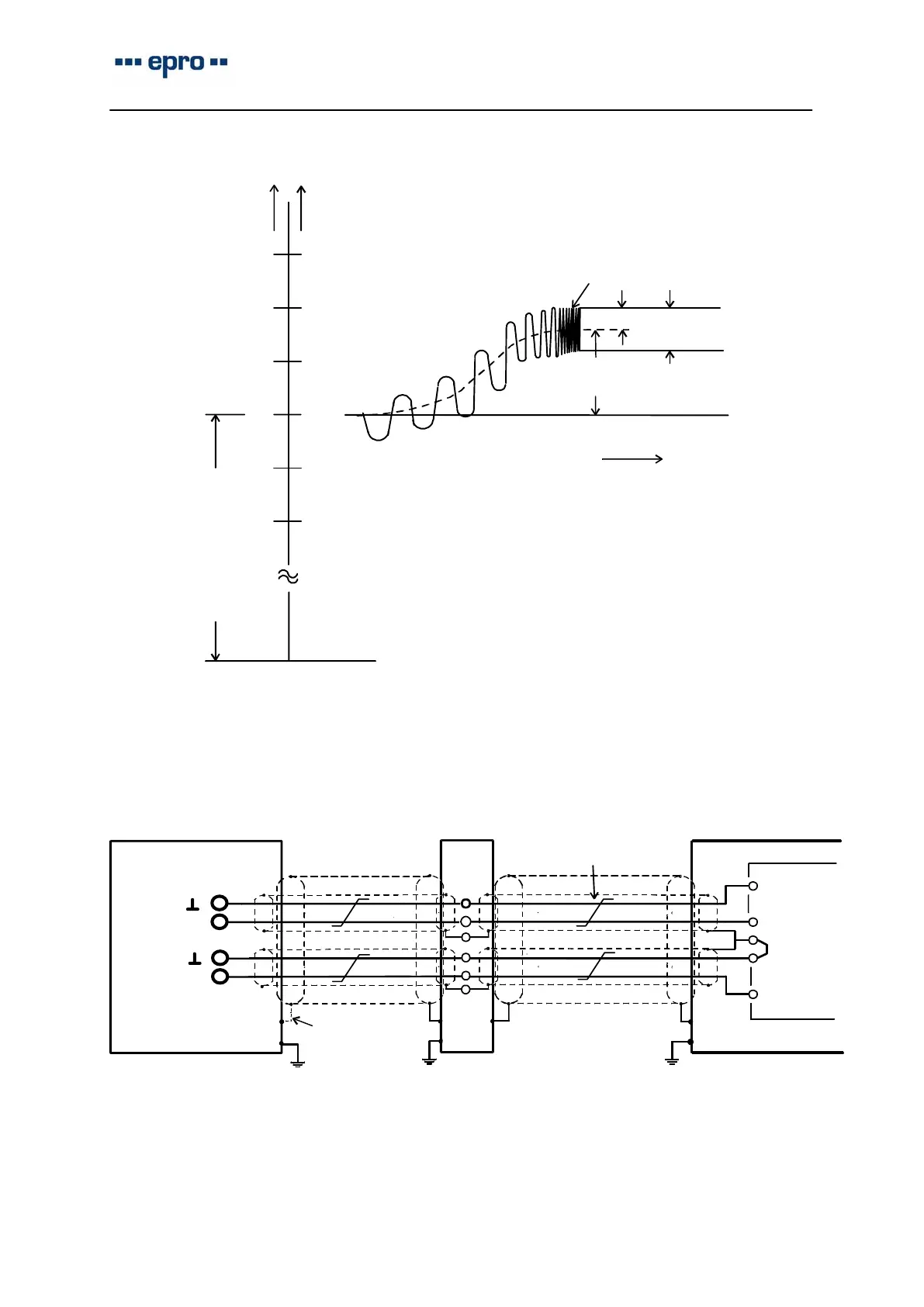
Quasi static displacement
Quasistatische Verlagerung
0 − peak
peak − peak
Shaft vibration signal
Wellenschwingungssignal
μm
V
50
100
150
−12,4
−12,8
−13,2
−50
−100
−11,6
−11,2
selected voltage
range: −4...−20V
−12,0
nominal distance a
nominaler Abstand a
N
N
time
Zeit
transducer face plane
Sensor: PR 6423
gewählter Spannungs−
bereich: −4...−20V
Sensorkopfebene
Fig 4: Shaft vibration signal, example / Wellenschwingungssignal, Beispiel
−24V
OUT
Input low
−24V
Common
0 V
Input high
CON 011
Converter
unct
on
ox
Cabinet
Monitor
see chapt. 1.3.1
siehe Abschn. 2.3.1
twistet wires
verdrillte Adern
Verteiler
Schaltschrank
Fig 5: Connection diagram, example / Anschlußdiagramm, Beispiel