Do you have a question about the Epsolar MT50 and is the answer not in the manual?
Provides guidance on inspecting the device, reading instructions, and avoiding environmental hazards and user service.
Details the MT50's capabilities: automatic identification, real-time data display, easy operation, power sharing, monitoring, alarming, and long communication distance.
Describes key operational functions including monitoring, parameter adjustments, and factory reset using the LCD and buttons.
Recommends checking controller compatibility and avoiding installation in high electromagnetic interference environments.
Details the steps for wall mounting, including locating holes, drilling, and fixing the frame with screws and expansion bolts.
Details steps for surface mounting, including drilling, using screws and nuts, and fitting screw plugs.
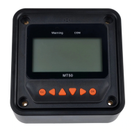
Identifies front panel elements including indicators, display screen, and buttons.
Describes the rear view and the RS485 communication and power interface.
Introduces the monitoring screen layout and key data elements like battery and PV status.
Details the meaning and display logic of various icons including day/night, charge current, battery status, and load status.
Identifies the six function buttons and illustrates their usage for navigating menus and editing parameters.
Details how to navigate the main menu using specific buttons to access features like Monitoring, Device Info, and Test Operation.
Explains the 14 pages of real-time monitoring, covering battery status, energy data, and controller information.
Details PV and Load operational status, voltage, current, and power, with navigation tips.
Details how to check product model, SN code, and other parameters using navigation buttons.
Explains the load switch test operation to check normal output and the steps to start/stop it.
Presents a diagram of control parameters for solar charge controllers, detailing battery settings and charging/discharging voltages.
Details parameters, default values, and ranges for battery type, Ah, temperature coefficient, and rated voltage.
Explains how battery voltage parameters are applied in 12V systems and scaled for higher voltage systems.
Details various battery charging settings, including voltages and durations, across different battery types (Sealed, Gel, Flooded, User).
Provides notes on duration ranges and rules for modifying user battery type parameters, with contact information.
Introduces the four load working modes: Manual, Light on/off, Light on+timer, and Time control.
Details the Manual and Light On/Off modes, and the Light On+Timer mode with its working times and conditions.
Details the Time Control mode for load operation, including working time definitions and diagrams.
Explains how to check and modify device parameters including software version, ID, backlight time, and internal clock.
Details how to modify the device password, noting the default password and its role in accessing settings.
Explains how to restore default parameter values and the factory default password.
Details how to check failure information, listing common failures and their corresponding details.
Details how to check and modify meter parameters including switch pages, backlight, and audible alarm settings.
Details the pin definitions for the data cable, specifying power inputs, RS485 signals, and ground connections.
Provides diagrams and dimensions for the remote meter, including faceplate and frame sizes, and notes on version updates.
| Brand | Epsolar |
|---|---|
| Model | MT50 |
| Category | Control Panel |
| Language | English |