2.1.1.1 Carriage Motor Driver Circuit
Carriage motor driver IC UDN2917EB (IC8) outputs a constant current to drive the carriage motor.
CPU M3772152BFP (IC2) determines the motor phase and speed, and then sends a signal to the
UDN2917EB carriage motor driver IC (IC8) via a 4-bit signal transmission line. The carriage motor is
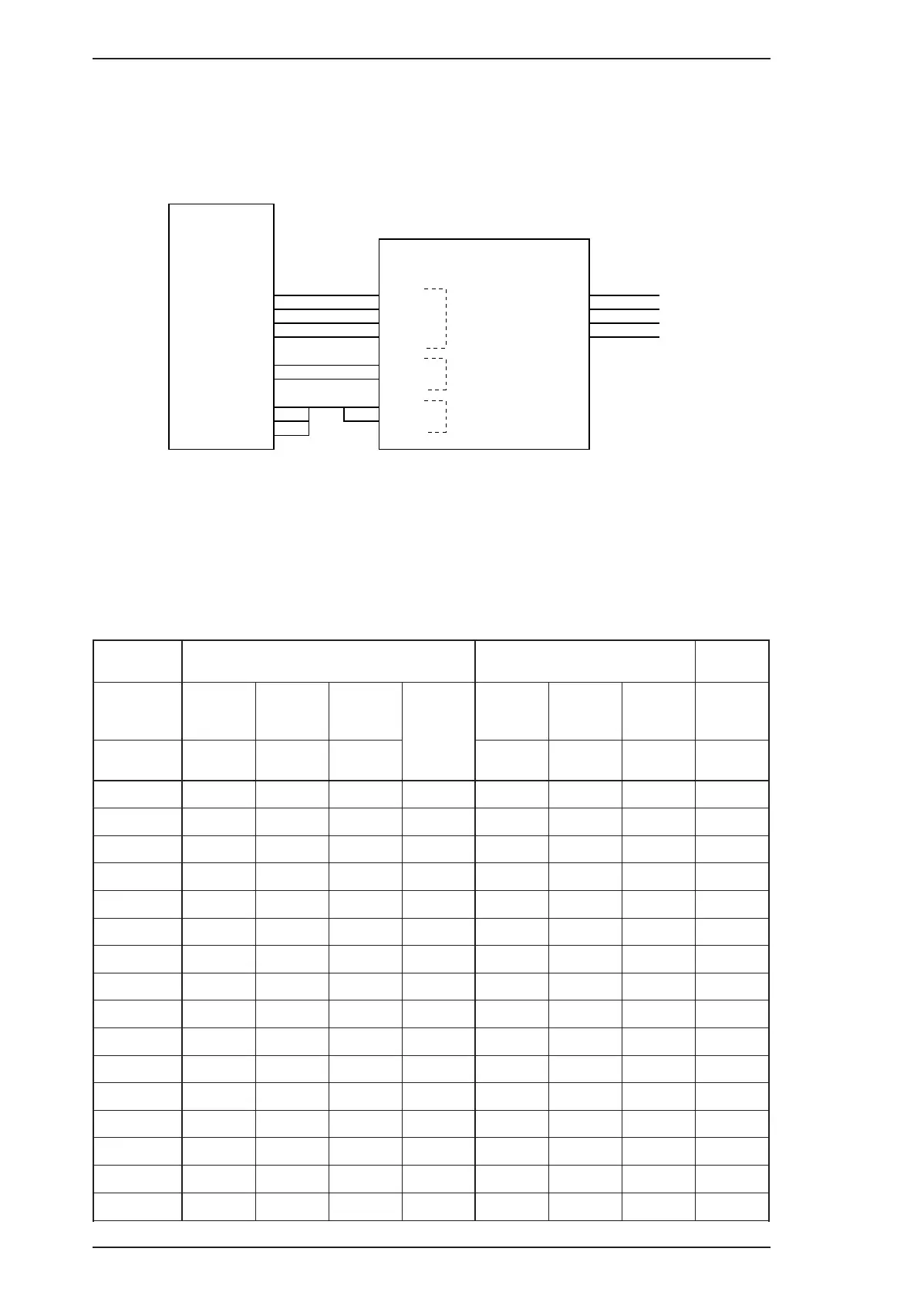
controlled by a 2W1-2 phase drive method. The figure below shows the carriage motor driver circuit
block.
Motor driver IC UDN2917EB controls the motor stepping direction and drive current with a
combination of six signals supplied from the CPU. PH1 and PH2 signals control the current flow
direction to determine the motor stepping position; and the I10, I11 and I20, I21 signals determine the
drive current supplied to each motor drive coil. Table 2-1 lists the combinations of these signals used
for the 2W1-2 phase drive control.
Table 2-1. Carriage Motor Drive Sequences
Sequence
Phase A
Phase B +
^
RTP03
RTP10 RTP11
Current
Duty
RTP02 RTP12 RTP13
Current
Duty
^
PH1 I11 I10 PH2 I21 I22 ^
0
000–10 110
1
0 0 0 –1 0 1 0 –1/3
2
0 0 1 –2/3 0 0 1 –2/3
3
0 1 0 –1/3 0 0 0 –1
4
11100 00–1
5
1 1 0 +1/3 0 0 0 –1
6
1 0 1 +2/3 0 0 1 –2/3
7
1 0 0 +1 0 1 0 –1/3
8
100+10 110
9
1 0 0 +1 1 1 0 +1/3
10
1 0 1 +2/3 1 0 1 +2/3
11
1 1 0 +1/3 1 0 0 +1
12
01101 00+1
13
0 1 0 –1/3 1 0 0 +1
14
0 0 1 –2/3 1 0 1 +2/3
15
0 0 0 –1 1 1 0 +1/3
IC2
M37721S2BFP
RTP10
RTP11
RTP12
RTP13
RTP03
RTP02
P105
P106
P107
IC8
UDN2917EB
4
3
2
1
5
6
19
18
17
I10
I11
I20
I21
PH1
PH2
VREF1
VREF2
2
1
23
24
43
26
44
25
A
-A
B
-B
6
3
18
21
CRA
CR-A
CRB
CR-B
Drive current level
Stepping direction
Trip current level
Figure 2-2. Carriage Motor Drive Circuit Block Diagram
Operating Principles EPSON Stylus COLOR 200 / EPSON Stylus 200
2-2 Rev. A