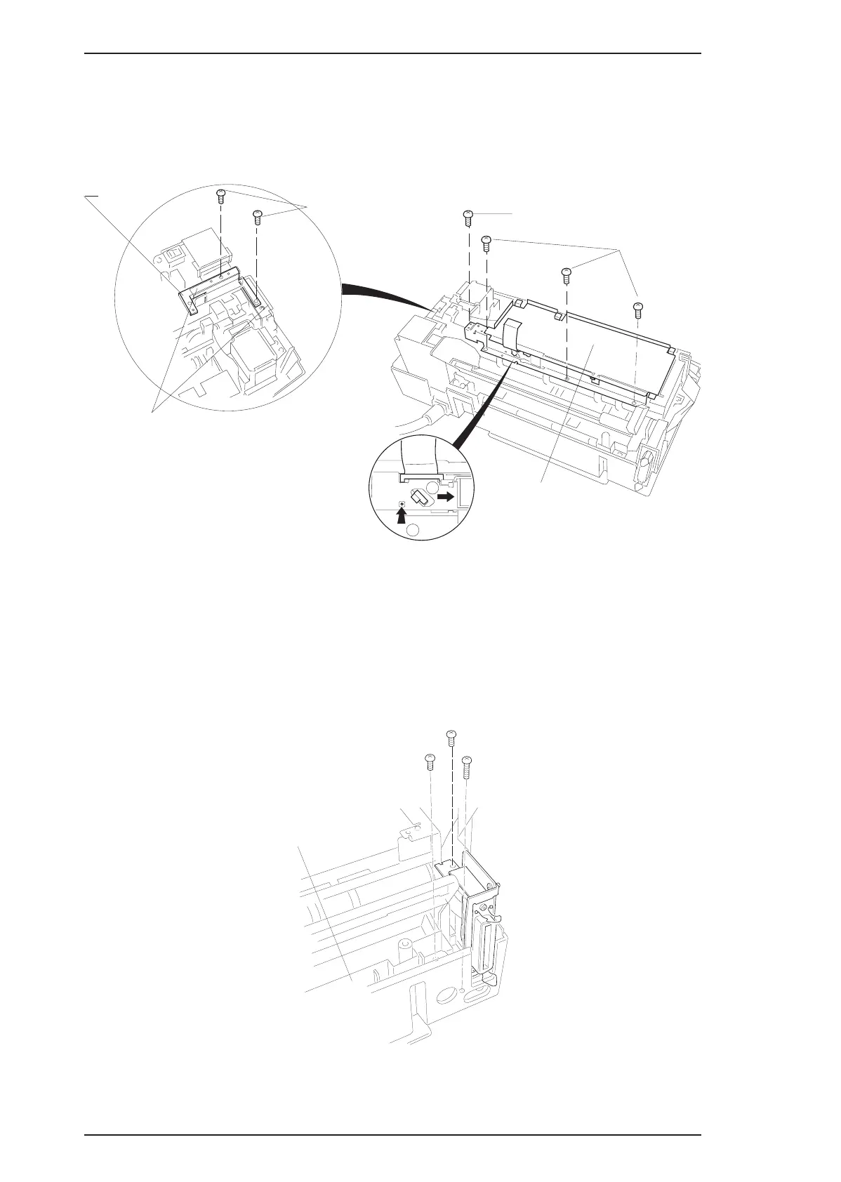
5.
Remove 3 CPS (M3×6) screws fixing the board frame to the mechanism and 1 CPS (M3x6) screw
fixing the metal stay between the board frame and the right side frame. Then remove the metal stay.
6.
Remove 2 CPS (M3×6) screws fixing the transpearency plate, then remove it.
7. Release the 3 hooks securing the FFC cable to the board frame then remove the board frame.
3.2.3 C160 I/F Board Removal
1. Remove the upper case (see Section 3.2.1).
2.
Remove 2 CPS (M3×6) screws and 1 CBB (M3×10) securing the C160 I/F Board to the mechanism and
bottom case.
3. Disconnect CN1 on this board; then remove it by lifting it up.
1
0
Transpearency plate
CPS(M3x6)
CPS(M3x6)
Board Frame
Metal stay
CPS(M3x6)
Figure 3-4. Board Frame and Metal Stay Removal
CBB(M3x10)
CPS(M3x10)
CPS(M3x10)
Grounding Plate
Figure 3-5. C160 I/F Board Removal
Disassembly and Assembly EPSON Stylus Color 200 / EPSON Stylus 200
3-4 Rev. A