EasyManuals Logo

Epson IMU G Series User Manual

Epson IMU G Series
19 pages
To Next Page IconTo Next Page
To Previous Page IconTo Previous Page
Page #10 background imageLoading...
Page #10 background image
Board Interfaces and Connectors
6 Seiko Epson Corporation Epson IMU_OEM7 Interposer Board
User Manual (Rev. 1.3)
6. Board Interfaces and Connectors
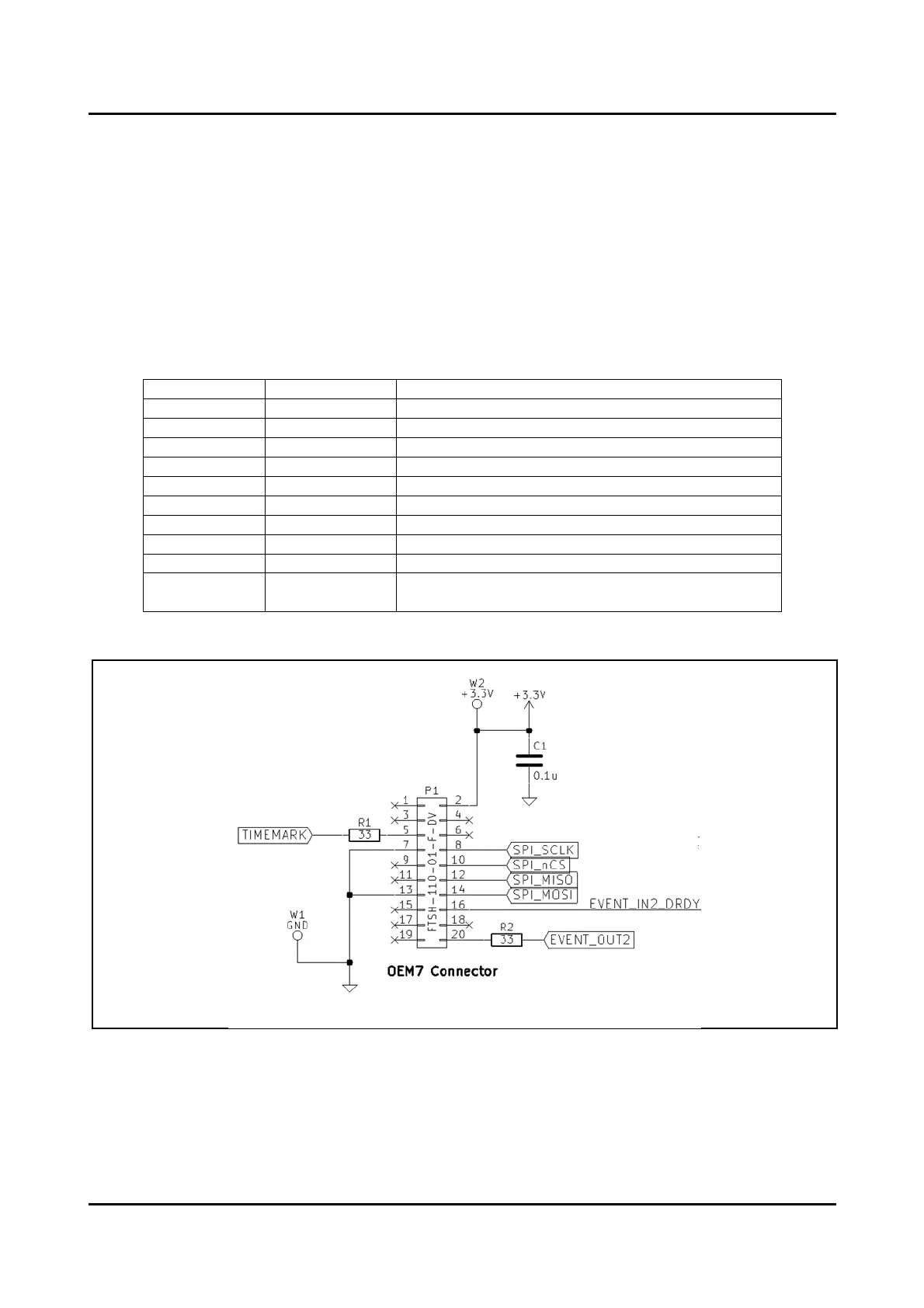
6.1. OEM7 Development Kit Connector P1
The NovAtel OEM7 Development Kit provides a mating connector and mounting holes for direct
connection of an external IMU Board. The EIIB supports this connection using a 2x10 1.27 mm pitch
header connector P1 (Samtec FTSH-110-01-F-DV). The EIIB also contains 3.45 mm diameter mounting
holes located on the four corners to secure the PCB to the NovAtel OEM7 Development Kit. For more
information regarding the recommended mounting hardware please contact NovAtel directly.
Table 6.1 OEM7 Connector P1 Pin Description
Pin Number
Signal Name
Description / Comment
2
VCC
3.3V supplied by OEM7 Development Kit
5
TIMEMARK
Optionally provides PPS
7, 13
GND
Circuit ground
8
SPI_CLK
SPI Clock (Supports SPI Mode 3 only)
10
SPI_nCS
SPI Chip select (Supports SPI Mode 3 only)
12
SPI_MISO
SPI Master In Slave Out (Supports SPI Mode 3 only)
14
SPI_MOSI
SPI Master Out Slave In (Supports SPI Mode 3 only)
16
EVENT_IN2
Connects to Epson IMU DRDY output
20
EVENT_OUT2
Optionally provides EVENT_OUT2 clock signal
1, 3, 4, 6, 9, 11,
15, 17, 18, 19
—
Not connected
The following diagram shows the P1 connector wiring.
Figure 6-1 OEM7 Connector P1 Wiring

Questions and Answers:

Question and Answer IconNeed help?

Do you have a question about the Epson IMU G Series and is the answer not in the manual?

Epson IMU G Series Specifications

General IconGeneral
BrandEpson
ModelIMU G Series
CategoryComputer Hardware
LanguageEnglish

Related product manuals