Board Interfaces and Connectors
8 Seiko Epson Corporation Epson IMU_OEM7 Interposer Board
User Manual (Rev. 1.3)
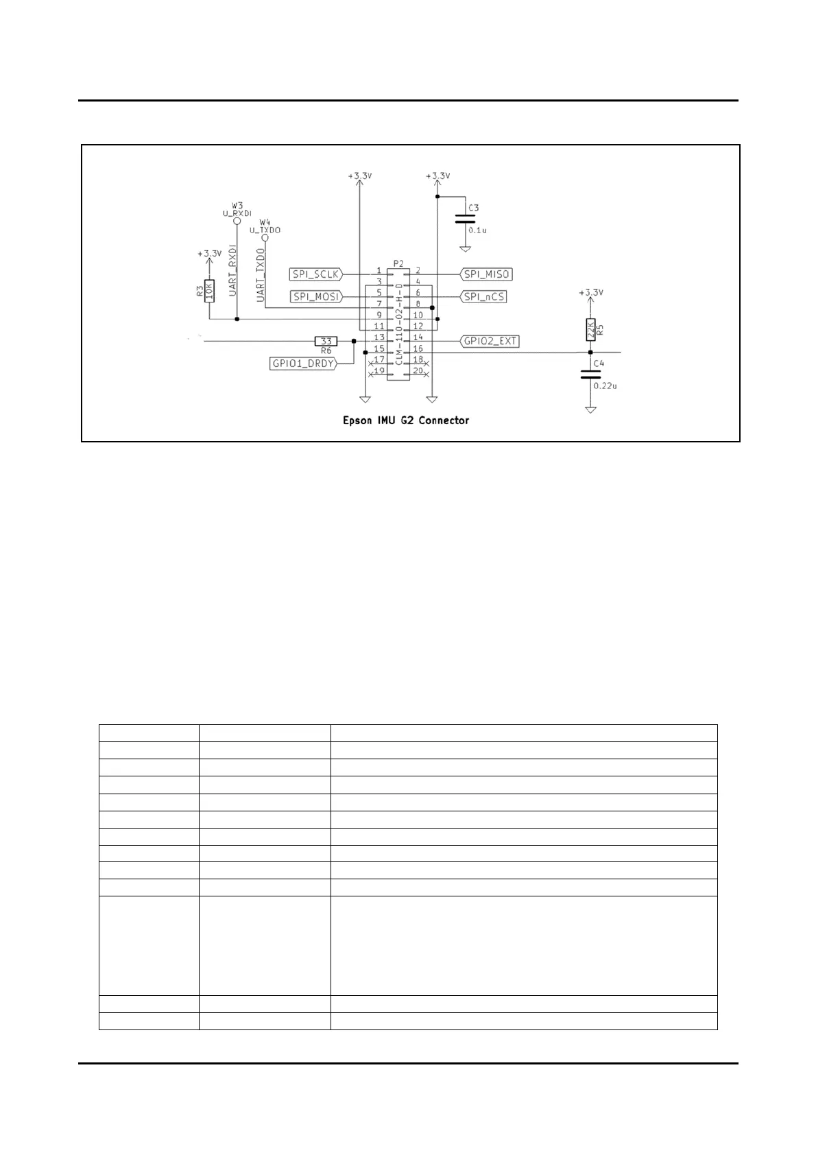
The following diagram shows the P2 connector wiring.
Figure 6-2 Epson G Series IMU Connector P2 Wiring
6.3. Epson V Series IMU Connector P3
The EIIB provides a 2x10 0.4 mm pitch socket connector P3 (Panasonic AXE120224) for directly
mounting the Epson V series IMU (M-V340). The P3 connector silk screen and mounting holes provides
a guide as to the correction mounting orientation of the Epson IMU.
NOTE: Take precaution to ensure the supported Epson IMU is mounted correctly on P3, or else it may
cause permanent damage to the IMU, EIIB, or OEM7 Development Kit.
NOTE: If using Epson V series IMU on P3, do not mount an Epson G series IMU on P2.
IMU signal that can be optionally connected to:
- OEM7 TIMEMARK (R1)
- OEM7 EVENT_OUT2 (R2)
NOTE: Do not mount both R1 and R2 at the same time.
Refer to Section Error! Reference source not found. Error! Re
ference source not found. for more information.
 Loading...