Configuration
Epson IMU_OEM7 Interposer Board Seiko Epson Corporation 5
User Manual (Rev. 1.3)
5. Configuration
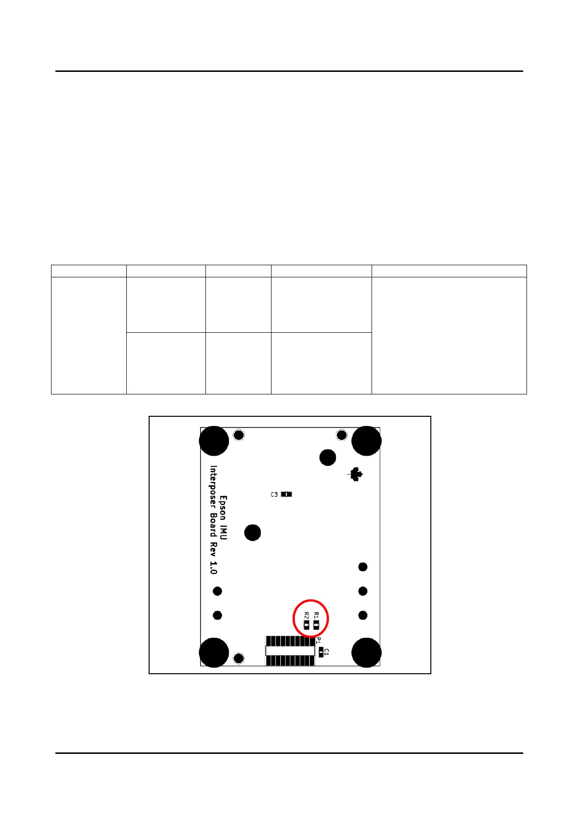
5.1. Configuration Resistors
The EIIB has two mountable 33 ohm 5% 0603 size resistors for optionally connecting either the
TIMEMARK or EVENT_OUT2 output signals from the NovAtel OEM7 Development Kit to the Epson
IMU GPIO2_EXT input. By default, neither R1 nor R2 resistors are mounted on the EIIB.
NOTE: This feature requires additional configuration settings on both the OEM7 Development Kit and
Epson IMU to make use of this function. Please contact NovAtel directly to inquire about the supported
Epson IMU models. Please refer to appropriate datasheets for additional technical information.
NOTE: DO NOT mount both R1 and
R2 at the same time. This will cause
TIMEMARK and EVENT_OUT2
output signals to be shorted
together and damage the OEM7
Development Kit.
If TIMEM ARK or EVENT_OUT2 is
not used, then R1 and R2 do not
need to be mounted.
 Loading...