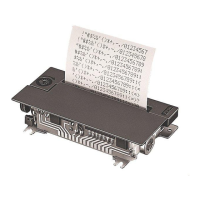
The provided document is a Designer's Guide for the Epson M-192G micro dot printer, marked as "Confidential." It offers detailed information for integrating the printer into an outer case, covering circuit design, component specifications, and guidelines for the physical enclosure.
Function Description
The Epson M-192G is a micro dot printer designed for integration into various systems. Its primary function is to print, likely on roll paper, using a dot matrix mechanism. The document details the internal circuitry for motor control, print solenoid drive, and fast paper feed trigger, indicating its capability for precise paper handling and printing operations. The "Designer's Guide" nature suggests it's intended for OEMs or system integrators who will build custom enclosures and integrate the printer into their final products.
Important Technical Specifications
The manual provides circuit diagrams and a list of major electronic components, which are crucial for understanding the printer's technical capabilities and for any custom circuit design or troubleshooting.
Major Electronic Components and their Specifications:
- 2SA1015 (Toshiba): Transistor with Ic (max) = -150 mA.
- DTA143Z (ROHM): Resistor-contained transistor with R1 = 4.7 kΩ, R2 = 47 kΩ.
- DTC143Z (ROHM): Resistor-contained transistor with R1 = 4.7 kΩ, R2 = 47 kΩ.
- 2SB1261 (NEC): Transistor with hfe (min) = 100, Ic (max) = -5A.
- 2SD1899 (NEC): Transistor with hfe (min) = 100, Ic (max) = 5A.
- STA413A (Sanken Electric): Zenor-diode contained transistor array.
- 1SS270A (Renesas): Diode.
- 2SA1020 (Toshiba): Transistor with Ic (max) = -2A.
- 1SS118 (Renesas): Diode.
Circuitry Details:
- Waveform Shaping Circuit for Timing Sensor and Reset Detector: This circuit, part of the Epson Evaluation Circuit, involves components like 1SS118, 2SA1015, DTC143, 74HC14 logic gates, and various resistors and capacitors (e.g., 1K, 470, 2.7K, 10K, 51K resistors; 1000pF, 0.1uF capacitors). It includes a timing sensor and a reset detector, crucial for precise operation and error handling.
- Motor Driver Circuit, Print Solenoid Drive Circuit, & Fast Paper Feed Trigger Solenoid Drive Circuit: This complex circuit, also part of the Epson Evaluation Circuit, utilizes components like DTC143, DTA143, 2SA1020, 2SB1261, 2SD1899, 1SS270A, and STA413A. It manages the motor, multiple print solenoids (A through H), and a fast paper feed trigger solenoid, indicating its ability to control various printing actions and paper movement.
Physical Dimensions (from Figure 2.2.1 and 2.2.2):
- Frame Thickness: 1 ±0.1 mm.
- Mounting Holes: #4, Ø2.6 ±0.1.
- Overall Dimensions (approximate, based on figures):
- Length: ~90.9 mm (Portion "E" when using a manual feed knob).
- Width: ~82.5 mm (Face "B").
- Height: ~49.2 mm (From Face "C").
- Copper Foil Edge Connector: 2.5 mm pitch.
- Paper Entrance Width: 57.5 ±0.5 mm.
- Clearance between paper holder and roll paper: 2.0 mm or less.
- Paper supply load at entrance: 0.3 N (approx. 30 gf) or less.
Usage Features
The document focuses on guidelines for designing the outer case, which directly impacts how the printer will be used and integrated into a larger system.
Installation Procedure for a Printer:
- Frame Protection: Care must be taken not to damage the printer frame during installation.
- Positioning: The printer should be positioned based on frame faces "A" (X direction) and "B" and "C" (Y direction).
- Mounting: Three screws should be inserted into mounting holes #1 to #4 and tightened. All four screws should not be tightened to prevent frame deformation and functional problems.
- Manual Feed Knob Consideration: If a manual feed knob is present, screw hole #4 cannot be used for fixing the case. The frame should be attached using screw holes #1 to #3. Portions E and F of the frame (marked with oblique lines in the figure) should guide the frame to suppress Z-direction shaking.
- Case Clearance: The case must be designed so that the manual feed knob does not touch the case when the frame shakes. The case should not touch the printer bottom except near the mounting holes.
Paper Entrance and Paper Holder Design:
- Alignment: The center of the paper holder on the case side must align with the printer's paper entrance width (57.5 ±0.5 mm).
- Clearance: Clearance between the case-side paper holder and the roll paper width should be 2.0 mm or less, but sufficient to prevent pressing or rubbing the paper roll.
- Low Load: Paper supply load at the entrance should be 0.3 N or less.
Paper Exit Design:
- Positioning: The paper exit position should be chosen to prevent ink stains on ejected paper.
- Foreign Object Prevention: Measures like a "coin barrier" are recommended to prevent foreign objects from falling into the equipment.
- Jam Prevention: A clearance between the case and printer is desirable to prevent paper jams if the exit is blocked.
Paper Cutter Design:
- Positioning: The paper cutter mounting position should be chosen to prevent ink stains on ejected paper.
- Noise vs. Feed Load: A more vertical paper path near the exit increases printing noise, while a more horizontal path increases paper feed load and potential problems. A balance must be struck.
- Safety: Special attention to safety is required to prevent users from injuring their hands on the paper cutter.
Case Design around the Manual Feed Knob:
- Clearance: The manual feed knob must not touch the case during operation.
- Protection: The knob should not project outside the case and should be protected.
Paper Roll-in Protection:
- The case design must prevent printed paper from being taken up again.
Other Notes on Designing the Outer Case:
- Noise Reduction: Openings (paper entrance, paper exit) should be as small as possible to minimize noise.
- Ribbon Cassette Removal: The case design should allow easy removal of the ribbon cassette by pushing the "PUSH" portion.
- Light Protection: The timing and reset sensor circuits use photosensors (LED and phototransistor pair), so the case must protect these sensors from external light to prevent operation errors.
- Vibration and Resonance:
- Apply buffer material (e.g., rubber) to printer mounting screws to prevent vibration transmission to the case.
- Improve case strength by thickening or adding ribs to reduce resonance.
- Grounding: Attach the ground wire using printer frame mounting holes (#3 or #4).
Maintenance Features
While the document primarily focuses on design and integration, some aspects touch upon maintenance considerations:
- Ribbon Cassette Removal: The design guideline for easy ribbon cassette removal (by pushing the "PUSH" portion) directly facilitates routine maintenance tasks like replacing the ribbon.
- Accessibility: The general emphasis on preventing damage during installation and ensuring proper clearances for paper paths (entrance, exit) implicitly supports easier access for potential maintenance or troubleshooting.
- Error Prevention: Guidelines like preventing foreign objects from entering the printer (coin barrier) and protecting sensors from external light contribute to the printer's reliability and reduce the need for frequent maintenance due to operational errors.
- Vibration Control: Designing the outer case to minimize vibration and resonance not only reduces noise but also potentially extends the lifespan of the printer components by reducing mechanical stress, thus lowering long-term maintenance needs.