Confidential
EPSON
TITLE
SHEET
REVISION
NO.
SHEETNEXT
C
M-192G
Designer’s Guide
(STANDARD)
7 6
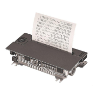
2.3 Paper Entrance and Paper Holder Design
1) The center of the paper holder on the case side must be aligned with the center of the paper
entrance width on the printer side. The paper guide must be able to guide paper which is 57.5 ±
0.5 mm wide.
2) Clearance between the paper holder on the case side and the roll paper width must be 2.0 mm or
less. However, the clearance must be sufficient to prevent the holder from pressing or rubbing
against both sides of the paper roll.
(See the overall dimensions figure for the dimensions of the paper entrance.)
3) Paper supply load at the paper entrance should be 0.3 N {approximately 30 gf} or less.
2.4 Paper Exit Design
1) See the figure in “2.13 Overall Dimensions” for the position for the paper exit of the case. (If the
paper is ejected right on the printer, it may be stained with ink.)
2) To prevent coins and other foreign objects from falling into the equipment, take measures such as
setting a coin barrier.
3) It is desirable to create a clearance between the case and printer so that no paper jam occurs even
if the paper exit is blocked accidentally.
2.5 Paper Cutter Design
1) See the figure in “2.13 Overall Dimensions” for the paper cutter mounting position. (If the paper is
ejected right on the printer, it may be stained with ink.)
2) The more the paper near the paper exit (i.e. paper cutter mounting position) approaches the vertical,
the more the paper resonates, making printing noise greater.
3) On the other hand, the more the paper approaches the horizontal, the more the paper feed load
increases. This may cause paper feeding problems.
4) Be sure to take special note of the safety so as to prevent the users from injuring their hands by
touching the paper cutter.
2.6 Case Design around the Manual Feed Knob
Because the Manual Feed Knob rotates while the printer is operating, the following items should be
considered:
1) The manual feed knob must not touch the case.
2) The knob must not project outside the case. The knob should be protected.
2.7 Paper Roll-in Protection
When designing the case, be sure to prevent printed paper from being taken up again.
2.8 Other Notes on Designing the Outer Case
1) The openings in the case, such as the paper entrance and paper cut position (i.e. Paper Exit) should
be as small as possible in order to minimize noise.
2) To remove the ribbon cassette, push the portion marked PUSH with a finger. Consider it in
designing the case. (See 2.13 Overall dimensions in the specification)
3) Since the timing sensor and reset sensor circuits use photosensors consisting of a LED and
phototransistor pair, the case must be designed to protect these sensors from external light, in order
to prevent operation errors.
4) While the printer is in operation, the case may resonate, making the printing noise greater. To
prevent this, it is desirable to design the outer case as follows.