Confidential
EPSON
TITLE
SHEET
REVISION
NO.
SHEETNEXT
C
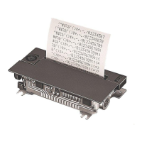
M-192G
Designer’s Guide
(STANDARD)
5 4
2. Outer Case Design Guide
2.1 Connections
A copper foil edge connector with a 2.5 mm pitch is fixed to the printer frame. The printer can be
connected to external circuits by soldering flat cables or lead wires to the copper foil pattern. When
selecting and using cables and wires, the current capacity must be taken into account for each of the
print solenoid signals, i.e. the common, A, B, C, D, E, F, G and H. Be sure that the soldered portions
are not placed under mechanical stress. (For the detailed dimensions, refer to the figures illustrating
the terminal assignment and the overall dimensions.)
2.2 Installation procedure for a printer (refer to Figure 2.2.1 and 2.2.2)
1) Be careful not to damage the printer frame when installing the printer.
2) For the X direction, position the printer as based on the frame face “A”.
3) For the Y direction, position the printer as based on the frame faces “B” and “C”.
4) Insert any three screws into mounting holes #1 to #4, and tighten them.
Take in consideration that the printer frame may be deformed and functional problems may occur if
all four screws are tightened.
5) For a printer with a manual feed knob, the case cannot be fixed with screw hole #4. The frame
should be attached to the case with screw holes #1 to #3.
Therefore, the frame should be guided at portions E and F (marked with oblique lines in the figure)
so as to suppress frame shaking in the Z direction as much as possible.
6) Even though the frame near the knob is guided at portions E and F, frame shaking in the Z direction
cannot be eliminated completely. Therefore, the case must be designed so that the manual feed
knob does not touch the case when the frame shakes up and down.
7) The case should not touch the printer bottom except near the mounting holes.