Epson Stylus NX125/T13/NX130 series Revision F
Disassembly/Assembly Details of Disassembling/Assembling by Parts/Unit 18
Confidential
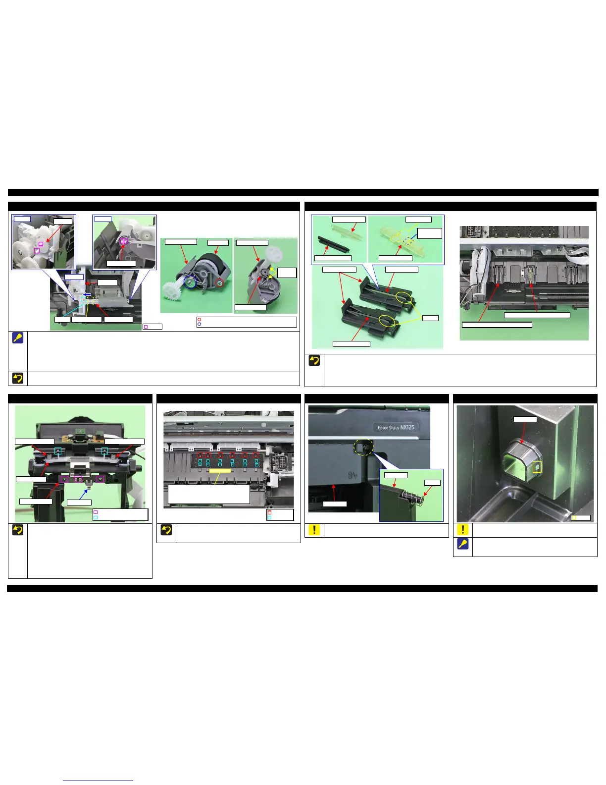
LD Roller Assy
When removing the LD Roller Assy, follow the procedure below.
1. Release the hooks (x2) and remove the Gear 23T.
2. Release the hooks (x2) and slide the Shaft Gear 24T to the 0-digit side until the concave section of the gear comes to the bearing part of the
Pick Assy.
3. Remove the LD Roller Assy upward.
When removing the LD Roller, remove the screws (x2) shown in the figure above.
When install the Torsion Spring, make sure to align the leg to the position as shown above.
Pick Assy
Step 2, 3
Shaft Gear 24TConcave sectionBearing
C.B.P-TITE SCREW 3x8 (TBD)
C.F.B-TITE SCREW 3x5 (TBD)
Hook
LD Roller Assy
Torsion Spring
Leg of the
spring
Housing Buckler
When installing the Friction Buckler and Friction Buckler R to the Housing Buckler, pay attention to the following instructions.
• Remove the Sheet BF2-A on the rear side of the Friction Buckler to be replaced, and secure the removed sheet with double-sided tape to the
new Friction Buckler.
• Install the friction bucklers to the Housing Bucklers with the cutouts facing forward.
Install the buckler to the position as shown above.
Friction Buckler R
Housing Bucklers Friction Buckler
Cutouts
Friction Buckler
Friction Buckler R
Friction Buckler
Sheet BF2-A
Double-sided
tape
Housing Buckler (Friction Buckler)
Housing Buckler (Friction Buckler R)
Carriage
When replacing the Carriage, be careful about the following and
remove the Grounding Plate, Guide Carriage, Compression Springs
from the Carriage to be replaced, then attach them to the new
Carriage as shown in the figure above.
Insert the protrusion of the Grounding Plate to the hole of the
Carriage, and align the dowels (x3) of the Carriage with the
positioning holes (x3) of the Grounding Plate.
Secure hooks (x2) of the Guide Carriage by attaching them on
the holes (x2) of the Carriage.
Grounding Plate
Guide Carriage
Compression Spring
Positioning Hole and Dowel
Hook
Protrusion
Compression Spring
Porous Pad Front Paper Guide
When installing the Porous Pad Front Paper Guide, align the pad
with the ribs and protrusions of the Platen. After installing the pad,
make sure to fit it evenly 1.5mm lower than the standard surface.
Standard surface:
In the area with concaves and convexes on the
Porous Pad Front Paper Guide, use the level
of the concave section as a standard surface.
Rib
Protrusion
Jam Cover
When removing the Jam Cover, be careful not to lose the spring
installed to the dowel on the right side.
USB Cover
The USB Cover cannot be re-used once it is removed. Whenever
the cover is removed, make sure to replace it with a new one.
When removing the USB Cover, cut the hook securing the USB
Cover with a nipper. Be careful not to damage the Upper Housing
then.

 Loading...