ERBAUER 254MM (10”) DOUBLE BEVEL SLIDING MITRE SAW
Bevel/Mitre Settings
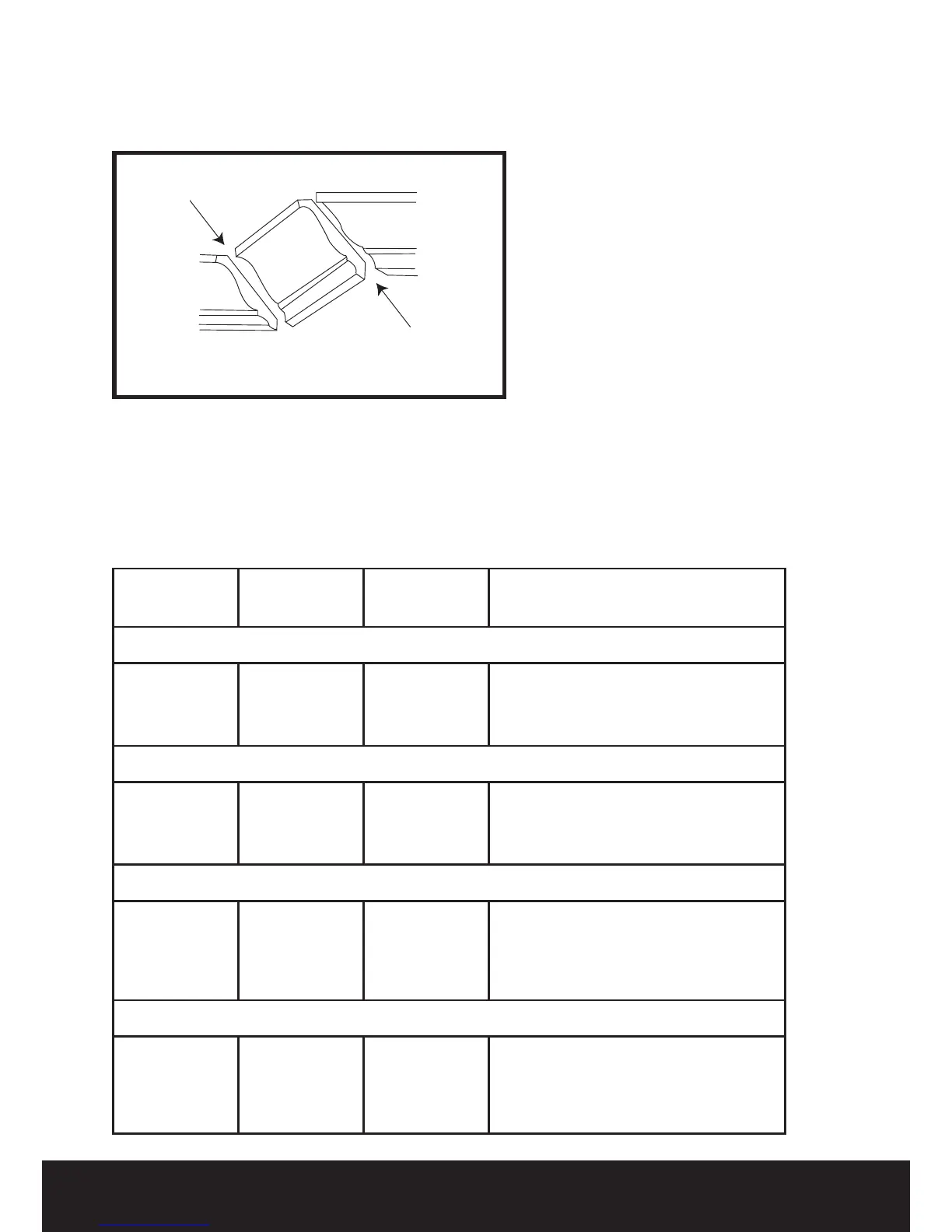
Settings for standard crown moulding lying at
on compound mitre saw table
Note: The chart below references a
compound cut for crown moulding ONLY
WHEN THE ANGLE BETWEEN THE WALLS
EQUALS 90
o
.
KEY BEVEL
SETTING
MITRE
SETTING
TYPE OF CUT
Inside Corner-Left side
IL 33.9
0
31.6
0
Right
1)Position top of moulding against fence
2)Mitre table set at Right 31.6
0
3)Left side is nished piece
Inside Corner-Right side
IR 33.9
0
31.6
0
Left
1)Position bottom of moulding against
fence.
2)Mitre table set LEFT 31.6
0
Outside Corner-Left side
OL 33.9
0
31.6
0
Left
1)Position bottom of moulding against
fence.
2)Mitre table set at Left 31.6
0
3)RIGHT side is nished piece.
Outside Corner-Right side
OR 33.9
0
31.6
0
Right
1)Position top of moulding against fence.
2)Mitre table set at RIGHT 31.6
0
3)RIGHT side is nished piece.
Fig 43
27
ERBAUER 216MM (8”) SLIDING MITRE SAW
Bevel/Mitre Settings
Settings for standard crown molding lying fl at on
compound mitre saw table
Note: The chart below references a
compound cut for crown molding ONLY
WHEN THE ANGLE BETWEEN THE WALLS
EQUALS 90°.
KEY
BEVEL
SETTING
MITRE
SETTING
TYPE OF CUT
Inside corner-Left side
IL 33.9° 31.6° Right 1) Position top of molding against
fence.
2) Mitre table set at RIGHT 31.6°.
3) LEFT side is fi nished piece.
Inside corner-Right side
IR 33.9° 31.6° Left 1) Position bottom of molding
against fence.
2) Mitre table set at LEFT 31.6°.
3) LEFT side is fi nished piece.
Outside corner-Left side
OL 33.9° 31.6° Left 1) Position bottom of molding
against fence.
2) Mitre table set at LEFT 31.6°.
3) RIGHT side is fi nished piece.
Outside corner-Right side
OR 33.9° 31.6° Right 1) Position top of molding against
fence.
2) Mitre table set at RIGHT 31.6°.
3) RIGHT side is fi nished piece.
IL
IR
OL
OR
Inside Corner
Outside Corner
Compound Cut Crown Moldings
Fig 42
Compound Cut Crown Mouldings