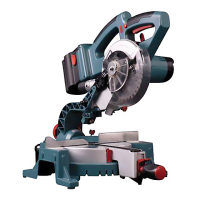
ERBAUER 254MM (10”) DOUBLE BEVEL SLIDING MITRE SAW
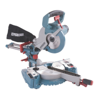
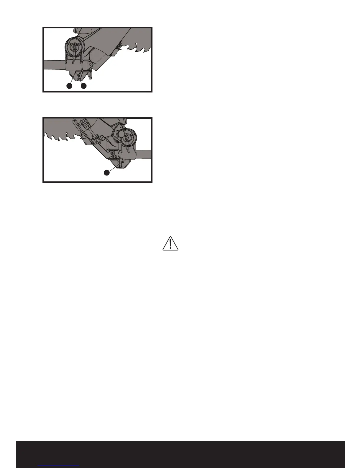
Three laser module mounting/adjustment screws are
provided. Two (1,2) are positioned on the LH side of
the laser housing, and one (3) on the RH side of the
laser housing. These screws gently hold the laser
module in place and on alignment by bearing on
the laser modules casing. It is important that during
any adjustment the pressure on the laser module
casing is maintained as closely as possible to the
factory setting. Do not over tighten any one screw –
damage to the laser casing could result.
(See g. 17&18)
B Adjusting the Angle of the Laser Guide
1) Loosen the single screw on the RH side of the
laser housing ½ a turn.
2)Turn the laser element in the desired direction to
adjust the laser angle.
3)Retighten the adjustment screw.
C Aligning the Laser Beam
1)Use the two adjusting screws on the LH side of
the laser housing.
2)Adjust both screws until laser alignment is
achieved.
Warning: Use only the correct sized
allen key when adjusting these screws. Turn one
screw at a time and only ¼ turn in either direction
before checking laser alignment. Maintain as far as
possible the original factory pressure setting that
these screws exert on the laser module.
Fig 18
Fig 17
1
3
2