EasyManua.ls Logo

Erbauer ERB2504SE - Storage for Push Stick and Spanner; Auxiliary Fence for Rip Fence; Auxiliary Fence for Mitre Gauge; Rip Fence and Mitre Gauge Installation

Erbauer ERB2504SE
30 pages
Print Icon
To Next Page IconTo Next Page
To Previous Page IconTo Previous Page
Loading...
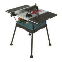
ERBAUER 250MM TABLE SAW
Note:
This tool is accurately adjusted before
shipping from the factory. Check the following
accuracy and readjust them if necessary in order
to obtain the best results in operation.
8
.
Installing the
push stick and blade
spanner
storage
1) Att
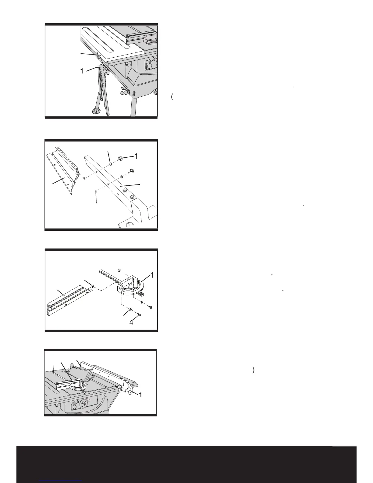
ach the hook (1) into the
hole (2) of the s
ide
table
for
push stick and blade
spanner
storage
spanner storage spanner
(
See
g.
8
).
9
.
Using auxiliary
fence
on the rip fence
A auxi
liary fe
nce should be used when ripping
material
su
ch as thin paneling to prevent the
mat
erial f
rom
catching bet
ween the bottom of
the fence and the table.
When performimg some
special cutting operations, you can add a
auxiliary
fence (3
) to
the
either side of the
rip
fence (4).
1)
Attach the
square nuts
to
the rip fence with the
clamp handles (1)
th
rough the washers (5) and
holes in the rip fence.
2) Slide
the
auxiliary
fence
(3) to the
square nuts (2).
3)
Tighten the
clamp handles
(See fi g. 9)
.
10.
Using auxiliary
fence
on the mitre
gauge
When performimg some special cutting
operations, you can add a
auxiliary fence (
2
) to
the
mitre gauge
(1).
1)
Attach the
square nuts
to
the mitre gauge with
the washers (3) and screws (4)
.
2)
Slide
the
auxiliary
fence
(2) to the
square nuts (5).
3) Tighten the
screws
(See fi g. 10)
.
11
.
Installing the rip fence and mitre
g
auge
1)
Lift upward on the rip fence handle (1) so the
rear holding clamp (2) is fully extended.
2) Place the rip fence on the saw table, lowering
the front of the fence onto the table fi rst.
3) Push down on the fence handle (1) to lock
4)
Place the mitre gauge (3) in the groove (4) on
the
table top.
(See
g.
11
)
.
Fig
8
Fig
9
1
2
Fig
10
Fig
11
1
2
3
4
5
1
2
5
3
1
2
3
3
4

Related product manuals