1 (5)
Uppgjord (även faktaansvarig om annan) - Prepared (also subject responsible if other) Nr - No.
SES/KTR Mats Andersson KTR97:2486
Dokansv/Godk - Doc respons/Approved Kontr - Checked Datum - Date Rev File
KTR M. Andersson 1997-12-07 A
97-2486-FAULT TRACING F800.doc
FAULT TRACING F800
1 GENERAL
This document provides fault tracing guide lines for field or first line
maintenance of all F800 versions. Maintenance instructions for the various
control and line panels used in F800 are not covered by this document.
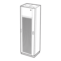
This document applies to F800 stations with cabinet SXK 107 2274/4
2 TOOLS AND INSTRUMENTS
To perform first line maintenance of F800 requires a minimum of tools and
instruments. The list below serves as a recommendation only.
Type
Model Comment
Radio test set Marconi 2945 or equivalent.
Wattmeter Bird 43 or equivalent
Test hand set Ericsson LPC 102 213
Voltmeter Fluke 77 or equivalent.
RF cable RG224 or equivalent Connections to F800
require N male
connector.
Test leads Connections to the
test hand set require
3.5 mm plugs.
Torx screwdrivers TX8, TX10 and TX15
In addition to this, normal hand tools are required.
3 FAULT TRACING
As with all fault tracing, start with a visual inception and make sure that all
cables are connected, the boards are inserted, etc.. To gain access to the
various indicators and test points in F800, you have to remove the front cover.
3.1 NORMAL SETTINGS
The interconnection board located in the cabinet has three (3) jumpers and
one rotary switch.
 Loading...