17(57)
Date Rev
DocumentnumberPrepared
Doc respons/Approved Checked File/Reference
1999-07-15 V
1531-BDV 113 08 Uen
INSTALLATION INSTRUCTION
Subject responsible
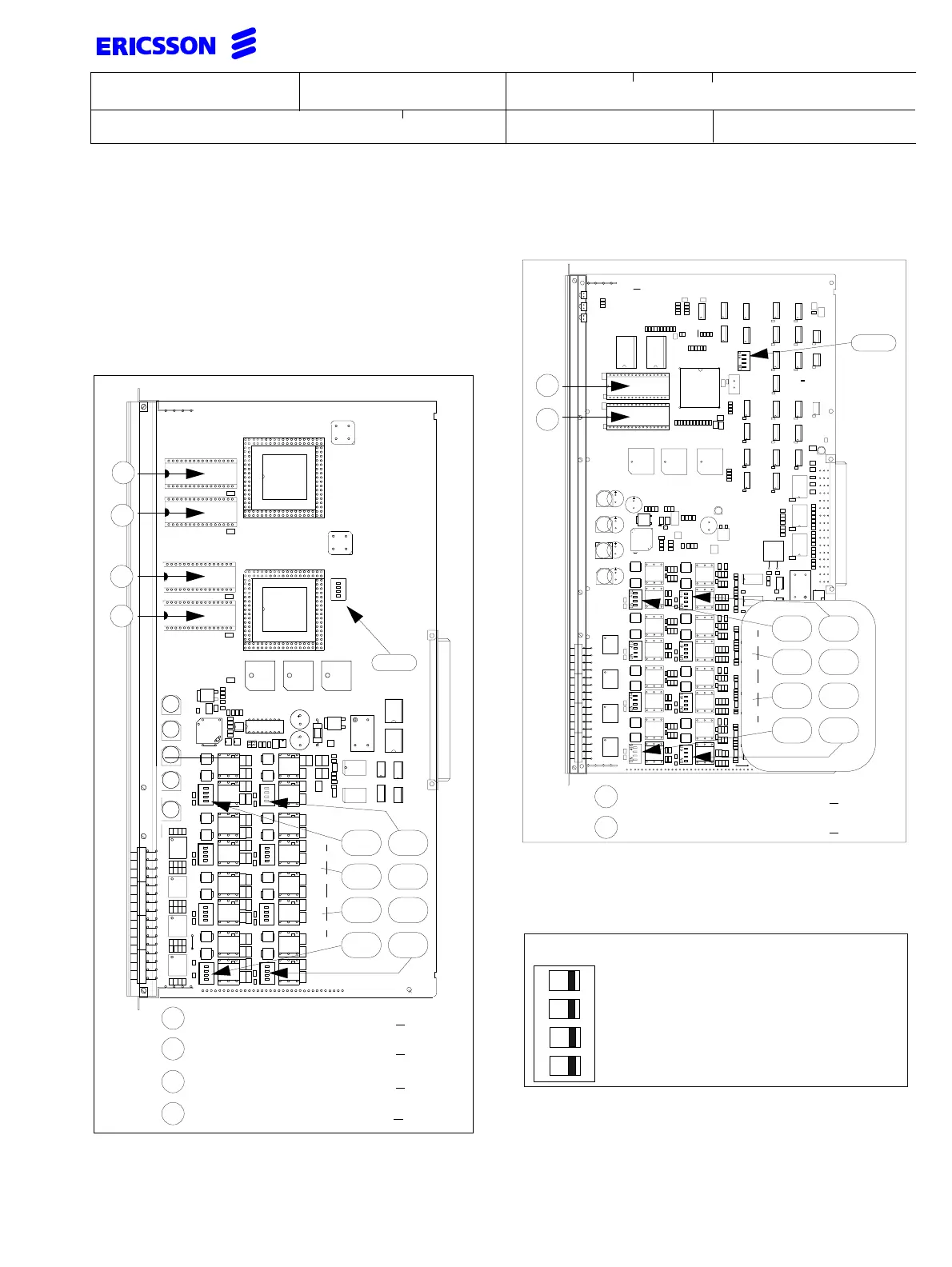
5.7 BTU-B (ROF 157 5121/_)
Applies for indices 1 and 3
The BTU-B provides connection for up to 8 physical
links and every physical link can be configured as a S-
or T-interface in point-to-point or multi-point mode. On
the S-interface every link provides remote power feed-
ing with 40V/50 mA = 2W and connection for up to 8
terminals.
5.8 BTU-B2 (ROF 157 5121/_)
Applies for indices 4 and 5
DIP-switches position 410-417
These switches control S- and T-interface termination
and S-interface power feeding on the link 0...7.
Note: at the end of each line a termination resistor
must be installed (e.g. in the last wall outlet).
The switch 1 selects the termination on the transmitter
interface and switch 2 selects the termination on the
ON
410 411
ON
414 415
412 413
416 417
418
ON
ON
ON
ON
ON
ON
ON
A
B
C
D
Insert PROM "RYS 102 521/ 1
A
B
Insert PROM "RYS 102 521/ 2
Insert PROM "RYS 102 521/ 3
C
D
Insert PROM "RYS 102 521/4
418
410 411
414 415
412 413
416 417
C
D
Insert PROM "RYS 102 521/ 3
C
D
Insert PROM "RYS 102 521/ 4
On factory delivery all switches are set to OFF
Connects 100 Ω send side termination
Connects power feeding ground
Connects -40V for power feeding
Connects 100 Ω receive side termination
ON
3
21
4