9(10)
Datum/Date Rev
Dokumentnr/DocumentnrUppgjord/Prepared
Dokansv/Godkänd - Doc respons/Approved Kontr/Checked Tillhör/Referens-File/Reference
1998-05-29 A
1531-BML 351 048 Uen
INSTALLATION INSTRUCTION
Faktaansvarig - Subject responsible
8 ALARM CONNECTION
8.1 ASB 150 01
The ALARM feature cannot be used in ASB 150 01.
8.2 ASB 150 02
Prerequisites: In order to install the alarm feature, the
CPU-D (ROF 157 5118/1) must have revision R1A/A
or higher.
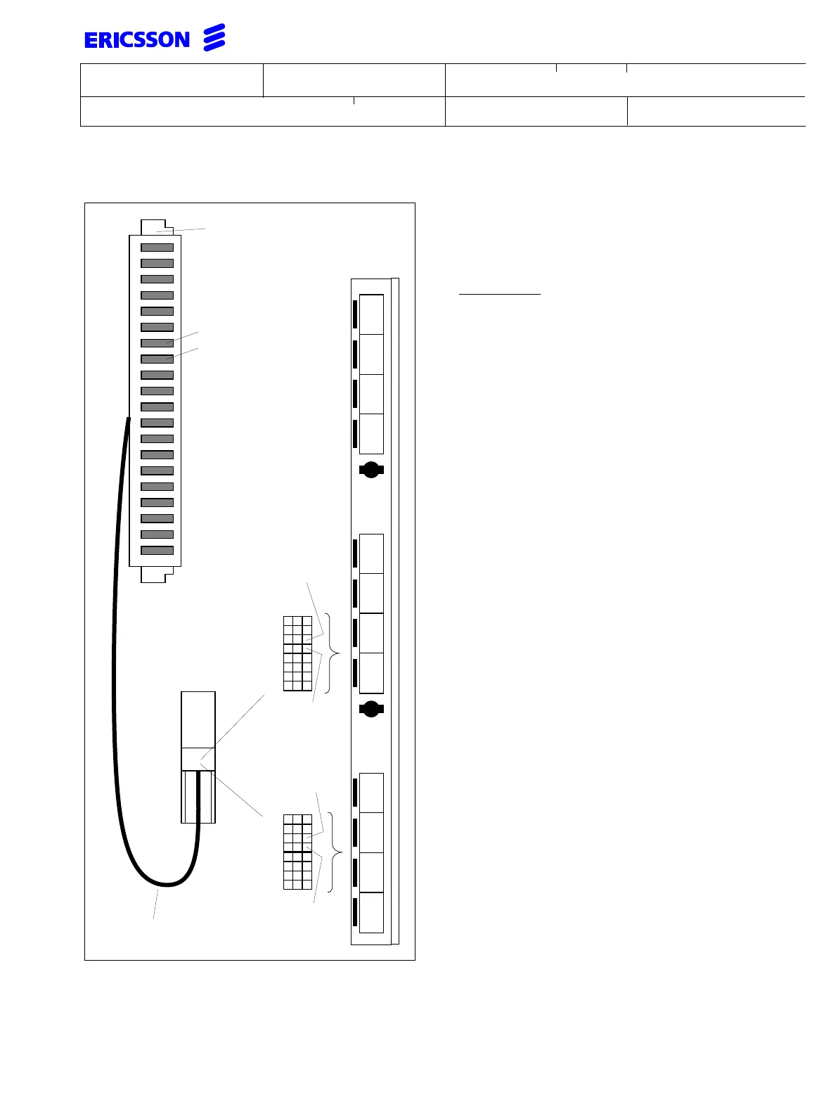
In case of mains failure the ALARM feature indicates
that the system is running on battery power. The Erics-
son standard I/O cable TSR 902 0444/1 carries all fea-
ture connections from the front connector of the
CPU-D board to the MDF connection block.
Should the system already use some of the system
features, (MUSIC input, ALARM output or
TEMPERATURE SENSORS) such a cable has alerady
been installed.
For the CPU-D, the connection is to be made to field 6
CD,EF, and for CPU-D_ the connection is to be made
to 4 EF,GH.
If the connection is to be done directly on the front of
the CPU-D_ board, use cable TRE 990 112/3000 and
connect the most positive wire (YELLOW) to pin C14
on CPU-D and pin C22 on CPU-D_. The most
negative (BLUE) is to be connected to pin C16 on
CPU-D and to pin C24 on CPU-D_.
1234567890
a
b
a
b
a
b
a
b
a
b
a
b
a
b
a
b
a
b
a
b
ab
cd
ef
oh
ab
cd
ef
gh
ab
cd
ef
gh
2
4
6
CPU-D
Common i/o cable
TSR 902 0444/1
YELLOW
10
12
14
16
18
20
22
24
Most
BLUE
MDF Connector
CPU-D/_
positive
(0 V)
Most
negative
(-48 V)
CPU-D_
CPU-D
A
BC
A
BC
18
20
22
24
26
28
30
32
Most
negative
(-48 V)
Most
positive
(0 V)