7(8)
Datum/Date
Rev
Dokumentnr/Documentnr
Uppgjord/Prepared
Dokansv/Godkänd - Doc respons/Approved Kontr/Checked
Tillhör/Referens-File/Reference
1999-07-15 C
1531-BML BS 101 01 Uen
INSTALLATION INSTRUCTION
Faktaansvarig - Subject responsible
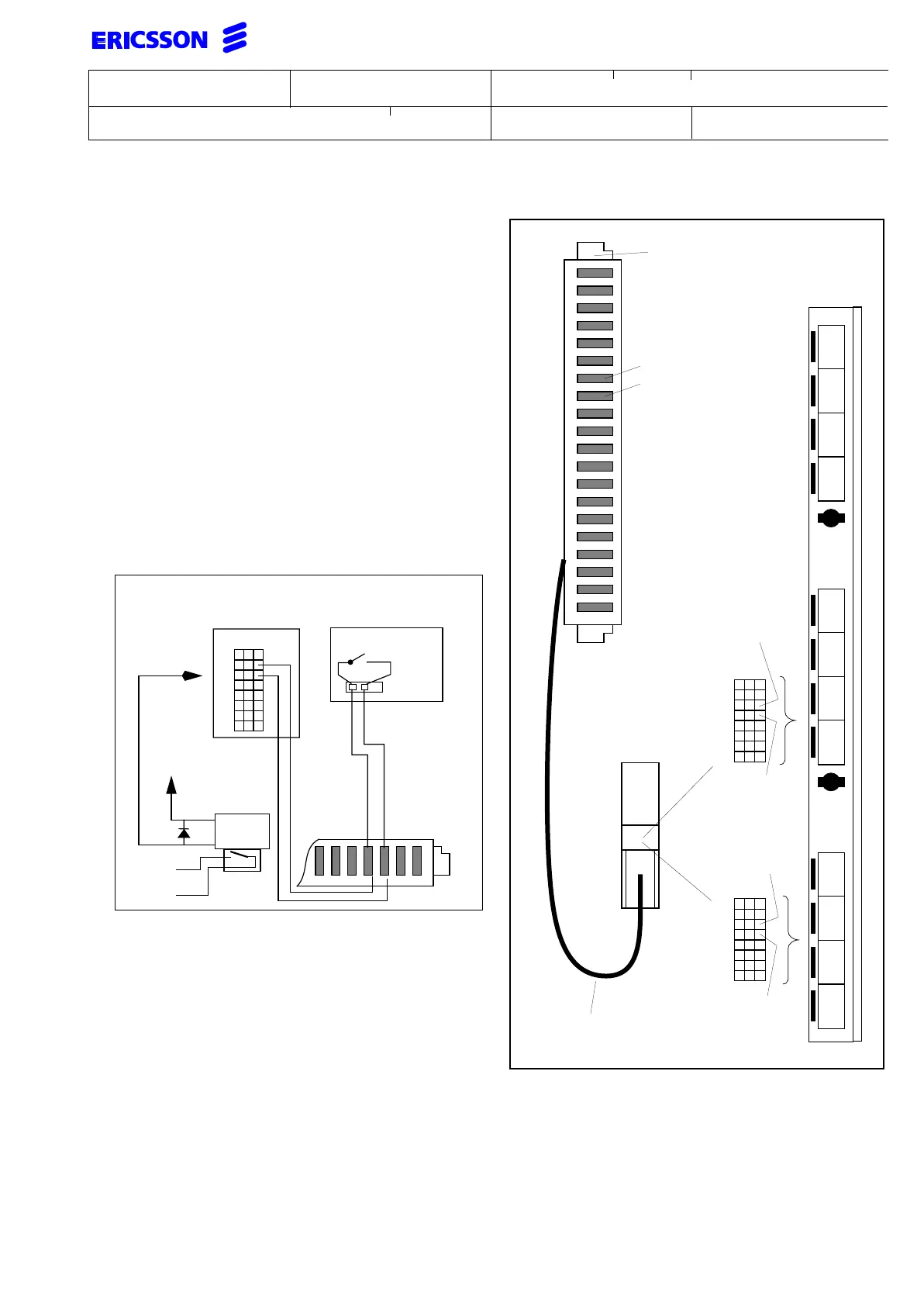
5 ALARM CONNECTION
For connection of the ALARM input to indicate that the system
is running on battery power, use an ERICSON standard
I/O cable or if an MDF is already equipped use a cable with
open ends to make the alarm connection.
Should the system be already using some of the system fea-
tures, (MUSIC input, ALARM output or TEMPERATURE SEN-
SORS), this cable has already been installed.
On the CPU-D, the connection is provided in field 6 CD,EF. On
the CPU-D/_, the connections are provided on field 4 EF,GH.
If the connection is to be done directly to the front of the
CPU-D, CPU-D/_ board, use cable e.g. TSR 901 0472/3
(open ends and 6m long) and connect the most positive wire
(YELLOW) to pin C14 on CPU-D and pin C22 on CPU-D/_.
The most negative (BLUE) is to be connected to pin C16 on
CPU-D and to pin C24 on CPU-D/_. Use the connection field
6 on the CPU-D and the connection field 4 on CPU-D/_.
The above figure shows an example for a 2 wire connection
for the alarm input and the alarm output connection.
a
b
a
b
a
b
a
b
a
b
a
b
a
b
a
b
a
b
a
b
ab
cd
ef
oh
ab
cd
ef
gh
ab
cd
ef
gh
2
4
6
CPU-D
Common i/o cable
e.g. w. open ends
YELLOW
10
12
14
16
18
20
22
24
Most
BLUE
MDF Connector
CPU-D/_
positive
(0 V)
Most
negative
(-48 V)
CPU-D_
CPU-D
A
BC
A
BC
18
20
22
24
26
28
30
32
Most
negative
(-48 V)
Most
positive
(0 V)
use last two
positions
A
BC
18
20
22
24
26
28
30
32
b
a
b
a
b
a
b
e.g. ROF 157 5124/_
MDF
CPU-D/_
Power supply
RELAY
to external
load
+12V
A 22