3(10)
Datum/Date
Rev
Dokumentnr/Documentnr
Uppgjord/Prepared
Dokansv/Godkänd - Doc respons/Approved Kontr/Checked
Tillhör/Referens-File/Reference
1998-05-29 A
1531-BML 351 048 Uen
INSTALLATION INSTRUCTION
Faktaansvarig - Subject responsible
4 LOCATIONS
4.0.1 Power Supply PSU 75 with battery charger (BML 351 048)
The switched mode power supply is available for applications demanding a higher current than supplied by the trans-
former and/or a battery backup for the PBX is required. This unit can also be used without battery backup.
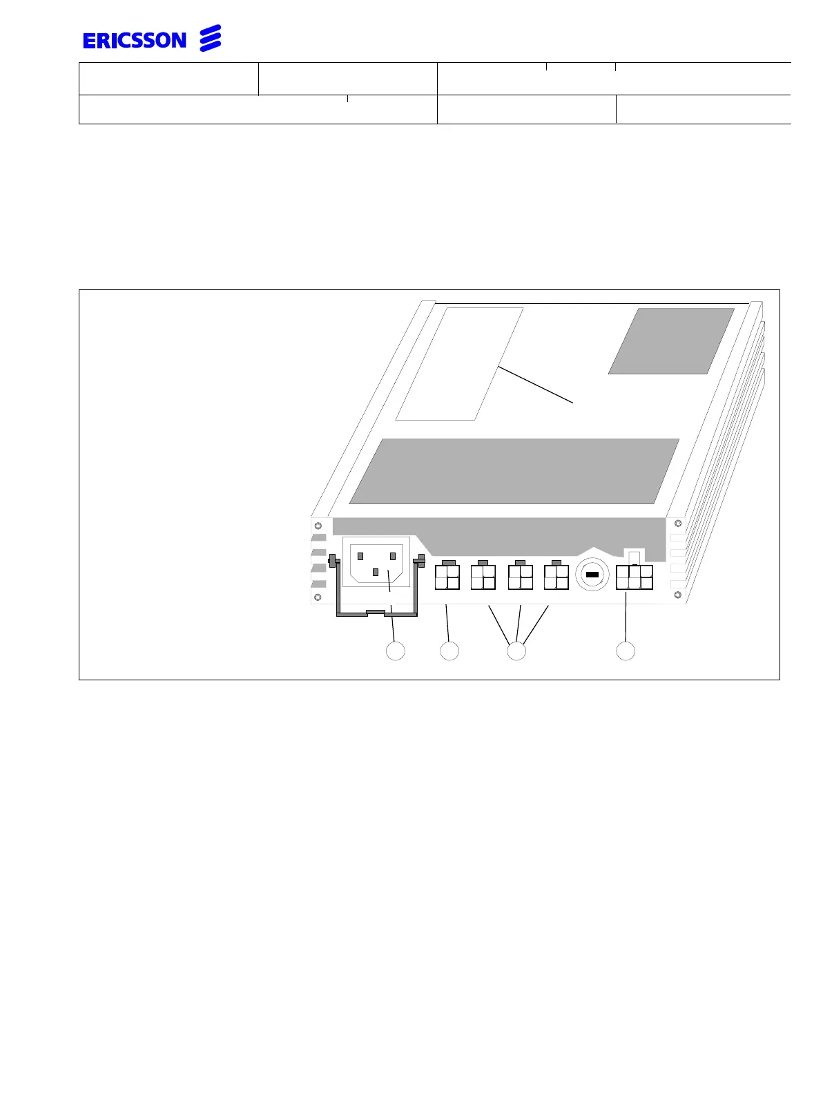
The physical connections on the BML 351 048 are listed below, together with a simple explanation of their purpose.
All connectors in the BML unit are keyed to prevent wrong cable connections.
• Batt is the 6-pin connector feeding the -48 VDC batteries in the battery cabinet or the integrated battery unit
• Btest/Alm is the output of the alarm relay inside the BML unit. The left part of the connector should be left
free and supports Btest, which is a functionality prepared for future use.The right part of the connector provides
the contacts for the alarm which closes the circuit during AC power outage
• D1 and D2 are the full rate -48 VDC outputs that feed the exchange cabinets, D3 is the -48 VDC output for
auxiliary equipment e.g. IC-CU, IC-LU, ISDN NT if needed. This output is current limited to 2.0A
• Mains is connected via an IEC 320 C13 (17) input connector for the 230 VAC. This input has a mechanical
locking for the straight power cord to prevent it from slipping off
• Fuse (T10A/250VAC) is the output fuse for D1 and D2
• F is a label stating the equipment, ratings serial number, production information, safety and CE marking.
NOTE: Mount the power supply unit securely to the cabinet with the supplied self-etching TORX screws .
F
D3Btest/Alm D2 D1 BattT10A 250V
Figure 1. Locations on BML 351 048
AB CD
220-240VAC