2(3)
Datum/Date Rev
Dokumentnr/DocumentnrUppgjord/Prepared
Dokansv/Godkänd - Doc respons/Approved Kontr/Checked Tillhör/Referens-File/Reference
1993-11-15 B
1/1531-ASB 150 02 Uen
INSTALLATION INSTRUCTION
Faktaansvarig - Subject responsible
1 GENERAL
This document describes how to connect the MUSIC
input to the ASB 150 02 system.
The description is valid for CPU-D, CPU-E and AUX
boards.
The MUSIC input can be used in the system to pro-
vide, for example MUSIC ON HOLD when connected
to either or both CPU-D (ROF 157 5118/1, -/2), CPU-E
(ROF 157 5124) and AUX (ROF 157 5119/1, -/2).
2 FUNCTIONALITY
The music output from a radio or tape recorder is fed
into the system via the CPU-D, CPU-E or AUX boards.
By programming the exchange, the output from the
connected equipment can be distributed throughout
the system.
3 DEPENDENCIES
CPU-D and AUX boards must have revision R1A/A or
higher and CPU-E board must have revision R1A.
Central software release R1 does not support this
function for the AUX board.
4 HARDWARE
INSTALLATION
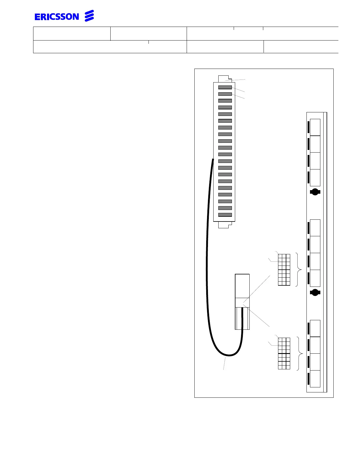
A twisted pair or a shielded cable should be connected
from the tape recorder output on a radio or tape
recorder to a1, b1 on the connector block of the
Ericsson standard MDF cable TSR 902 0444/1.
The Ericsson standard MDF cable will carry all
connections of the CPU-D, CPU-E and AUX options, to
the MDF. If any of the board options are installed in the
system, this cable is already installed.
It is also possible to connect a cable from the music
equipment directly to the input of the CPU-D, CPU-E or
AUX board front. The connection should then be made
to pins A10, A12 of connector 6 for CPU-D/1 or AUX/1
and to pin A18, A20 of connector 4 for
CPU-D/2, CPU-E and AUX/2.
1234567890
a
b
a
b
a
b
a
b
a
b
a
b
a
b
a
b
a
b
a
b
ab
cd
ef
oh
ab
cd
ef
gh
ab
cd
ef
gh
2
4
6
CPU-D/1
Common i/o cable
TSR 902 0444/1
10
12
14
16
18
20
22
24
MDF Connector
CPU-D/2
CPU-E
CPU-D/2
CPU-E
CPU-D/1
A
BC
A
BC
18
20
22
24
26
28
30
32
MUSIC
input
AUX/1
AUX/2
MUSIC
input
MUSIC
input
AUX/1
AUX/2