6(11)
Datum -
Date
Rev
Nr -
No.
Uppgjord (även faktaansvarig om annan) -
Prepared
(also subject responsible if other)
Dokansv/Godkänd -
Doc respons/Approved
Kontr -
Checked
File
1998-04-20 B
1531- DBC 211 01 Uen
INSTALLATION INSTRUCTIONS
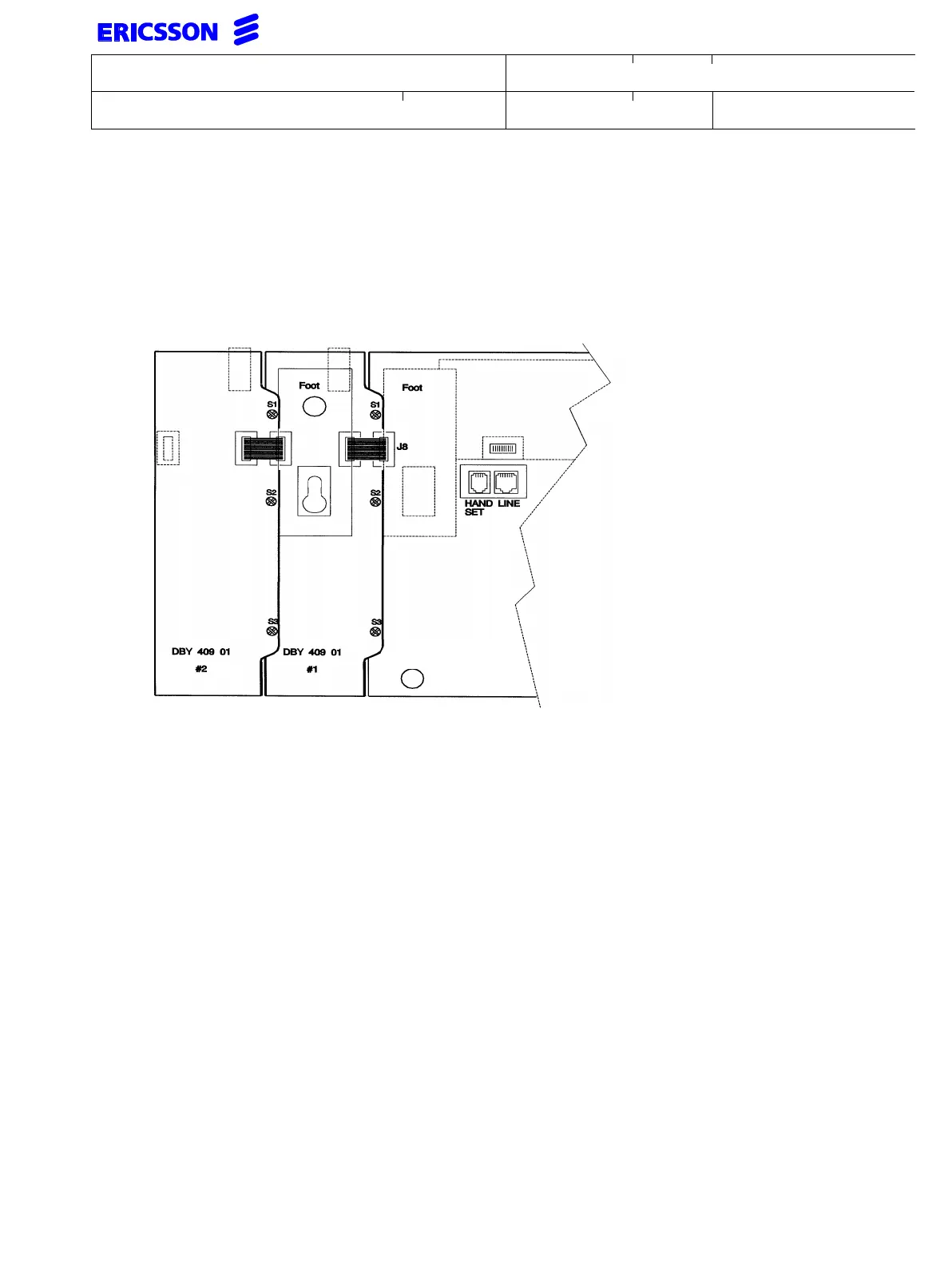
If a second DBY 409 01 is to be installed, do as follows
• The procedure above is repeated for the second DBY 409 01
• Move the foot to the second DBY 409 01
A third DBY 409 01 cannot be connected
Rear view of DBC 213 01 with two DBY 409 01 connected.
8.2 Post installation measures
Connect the DBC 213 01 with the DBY 409 01 to the extension line and verify that the bottom
LED at each DBY 409 01 is activated during start-up. Establish a call using the keys located on
the DBY 409 01.
8.3 Installation of key panel DBY 409 02 to DTS DBC 213 01
• Make necessary arrangements to avoid electrostatic discharges.
• Disconnect the OPI from the exchange
• Avoid if possible to touch the contacts
• Break off the blinder covering the contact J8
• Connect the cable from DBY 409 02 to contact J8
• Attach DBY 409 02 to DBC 214 01 and secure it with the three screws (S1, S2 and S3)
If additional DBY 409 02 are to be installed (maximum four), do as follows
• The procedure above is repeated for the second DBY 409 02
DTS type
DBC 213 01