11(11)
Datum -
Date
Rev
Nr -
No.
Uppgjord (även faktaansvarig om annan) -
Prepared
(also subject responsible if other)
Dokansv/Godkänd -
Doc respons/Approved
Kontr -
Checked
File
1997-11-19 A
1531-DBC 214 01 Uen
INSTALLATION INSTRUCTIONS
9.6 Connection of tape recorder
A tape recorder can be connected for recording of calls. The recorder can be connected either to
jack J3 fig 9-1or jack J4 fig 9-1. In jack J3 pins a and b and in jack J4 pins 1 and 6 are used for
tape recorder output. The levels are adapted for 600 ohms load impedance. When using a tape
recorder or equivalent LED 6 shall be set to OFF.
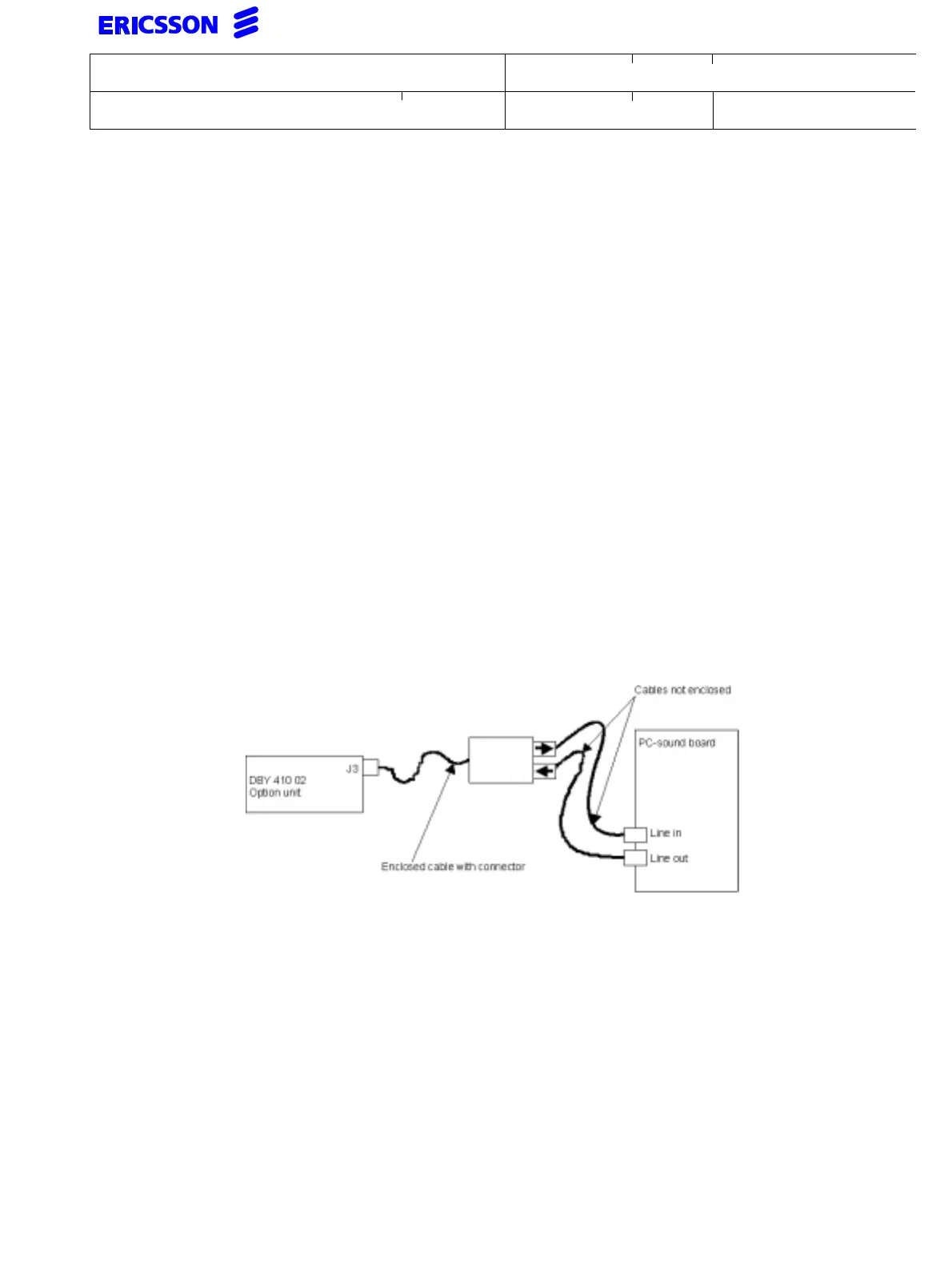
9.7 Connection of PC-sound board
A PC sound board or equivalent can be connected to jack J3 fig 9-1. When connecting a “sound
board” two different modes can be selected. For easy connection of the "sound board" the
enclosed cable, RPM 130 017/1 can be connected to jack J3 fig 9-1.
The outgoing signal from the option unit, marked --> on the cable, shall be connected to the
input, often called LINE IN, of the "sound board". If applicable the incoming signal to the option
unit, marked <-- on the cable, shall be connected to the output, often called LINE OUT, of the
"sound board". See fig 9-3.
Recording mode: This mode can be used when the “sound board” shall record an ongoing
conversation. This mode is the same as tape recorder mode i.e. LED 6
is set to OFF.
PC/AUDIO mode: This mode can be used when the “sound board” shall be used for con-
versation. This mode requires the LED 6 to be set to ON.
Connection of PC-sound board with cable RPM 130 017/1
9.8 Post installation measures
Connect the extension line and check that a call can be established and check that
the installed extra equipment can be used in both directions (if applicable).